Optimising Image Rasterisation In Nuke
How to preserve the most amount of image quality when compositing…
How to preserve the most amount of image quality when compositing…
Work On The Original
There are a few compositing equivalents to ‘photocopying a photocopy of a photocopy’, that you should avoid when working in Nuke.
You might already know all about the importance of optimal filtering and concatenation. Or rendering images with a high enough bit depth. However, you may not be familiar with how to optimise the image rasterisation that's happening in your composite.
Raster Vs Vector Images
There are two main types of digital images: raster (or bitmap) images and vector images.
Raster images are built from pixels. This is what we're mostly working with in Nuke. The scan you're working on in your shot is a raster image, for example.
The more pixels a raster image has, the higher quality it'll be (or will have the potential to be) due to the increased resolution and detail. However, scaling raster images up or down will lead to a loss in image quality because Nuke has to approximate and ‘invent’ new pixels based on neighbouring pixels.
Vector images, on the other hand, consist of mathematical formulas that define the components – the shapes, borders, and colours – that make up the image.
There are no pixels in a vector image, and the mathematical formulas can recalibrate to any size. That means you can scale the image up or down as much as you want without any loss of image quality.
Rasterisation
Rasterisation is the process of converting a vector image (or object) into a raster image, i.e. converting the mathematical descriptions into a grid of pixels.
When you draw a roto shape in Nuke, the spline is a mathematical formula. Internally in the Roto node, your roto shape is a vector image. It's only when it's output from the Roto node that the image is rasterised, i.e. turned into pixels.
It's useful to be aware of that fact when compositing:
Let's say that you have a shot where the camera dollies forward towards an object. Your task is to replace something behind the object, and so you’ll need to roto it. To start, you might 2D track the object to simplify the roto work.
After tracking, I see a lot of people drawing a roto shape for the object on a frame, and then connecting a Transform_MatchMove node (generated from a Tracker set to the same reference frame) – or even connecting the Tracker node itself, directly – to the Roto node.
This is typically 'fine' if you drew the roto shape on the frame where the object is the largest in frame. (Scaling pixels down usually gives a better result than scaling them up).
But that's not always the case. And if you take a look at your rasterised roto shape when it's being scaled up, you'll start to see pixelation along the edges – from image degradation:
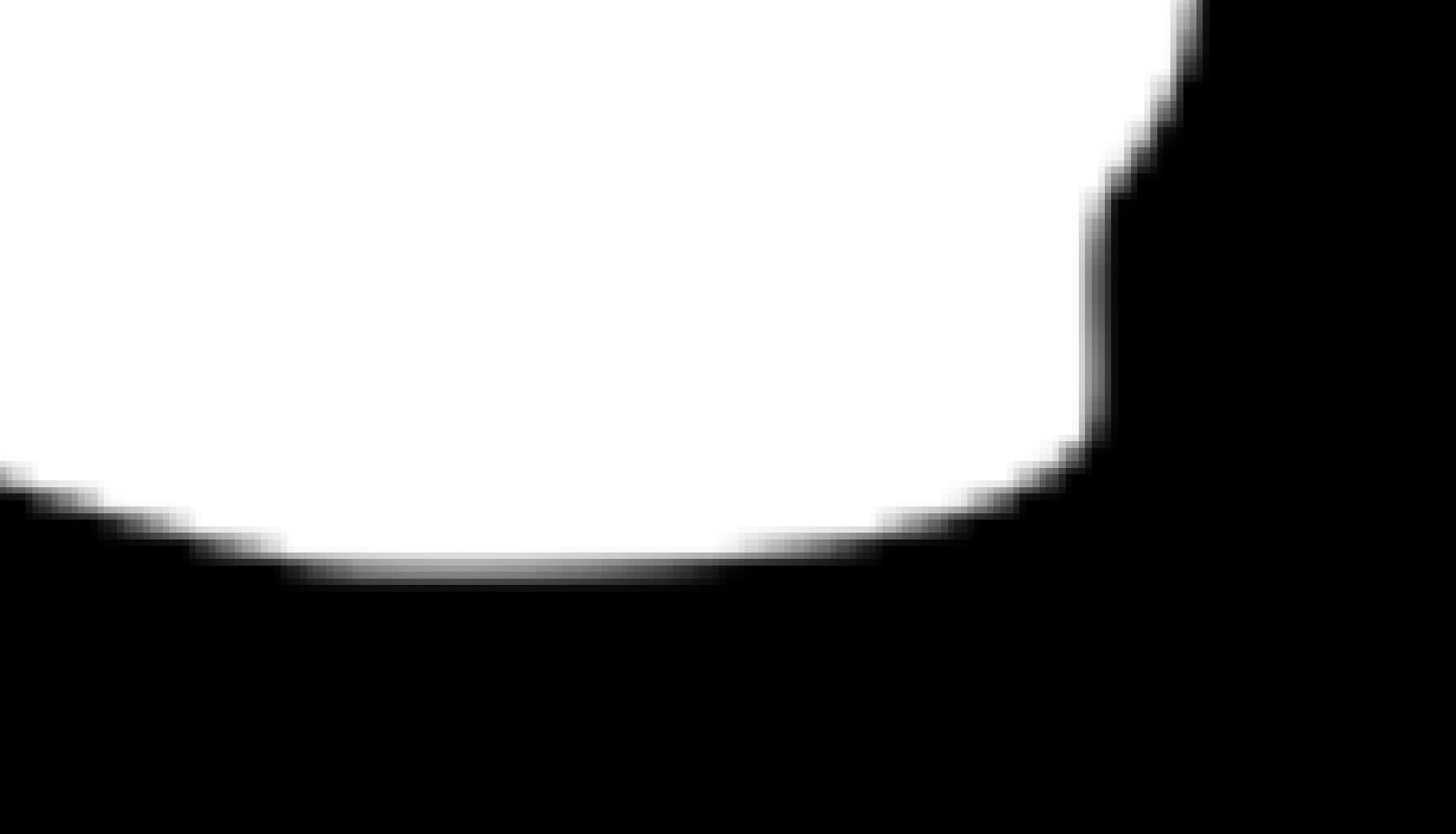
An example roto shape being scaled up post-rasterisation.
Instead, it's better to apply the matchmove to the roto shape inside the Roto node. – While the roto shape is still a vector image, and can be moved around and scaled up and down without any loss of quality:
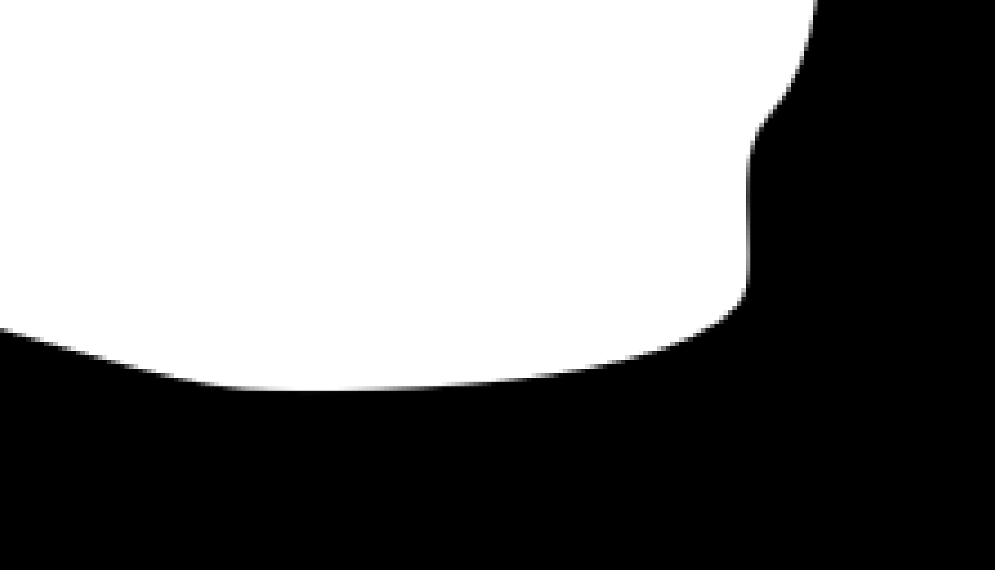
The same roto shape being scaled up pre-rasterisation.
As you can see above, matchmoving the roto shape pre-rasterisation yields a much sharper image (particularly when there is a scale-up involved), and the muddy pixelated mess from before is gone.
In order to do that, link the tracking data from the Tracker node directly to the Roto node:
Open up the properties of both nodes and go to the Transform tabs of each.
Select the Root layer in the Roto node and hit Ctrl (Cmd) and Left Mouse Button drag the Animation menu buttons next to the translate, rotate, scale, and center knobs in the Tracker node to their respective buttons in the Roto node.
I would suggest renaming the Root layer to RootTRACK, or similar, in order to make it abundantly clear that there is now tracking data linked to it.
Linking a Roto node to a Tracker.
By applying the tracking data to the Root layer, every spline in the Roto node that you have created, and any that you create going forward, will automatically get matchmoved. And, they will retain the highest possible image quality.
The same thing applies to pretty much any node with either a Transform tab or transformation settings somewhere in its properties – like the Noise node, the GodRays node, the RotoPaint node, the GridWarp node, the SplineWarp node, and so on. If possible, perform the transformations internally within the nodes instead of on their rasterised output, in order to get a better image quality.
Note that if you have a matchmoved CornerPin node (for example from Mocha) instead of a Tracker/Transform node, then you can’t link it directly to the Roto node like shown above. Instead, you’ll have to convert it via a transform matrix:
Convert a CornerPin node to a Roto node using the Convert Node Matrix tool.
Let’s visit the next dimension.
Rasterising 3D Scenes
Rasterisation is not only for converting 2D vector images into raster images.
3D scenes/objects are also rasterised in order to turn them into a raster image that we can view in 2D. Nuke’s ScanlineRender node rasterises the 3D scene and outputs pixels, for example. (And it even has a few more filtering options than the Transform node).
When viewing for example a Sphere through a Camera using the ScanlineRender node, the Sphere is a vector object which gets rasterised.
You can affect the image quality that’s output by the ScanlineRender node in three ways:
- Adjusting the quality of the input geometry and textures. That is, increasing the subdivisions and detail in the geometry, and using more detailed, higher resolution textures.
- Adjusting the different settings in the ScanlineRender node, such as filter, antialiasing, and samples.
- Controlling the amount of pixels the ScanlineRender node outputs. That is, connecting a Reformat node to the bg input, and choosing a format that will give you the level of detail you need.
The first two points are pretty self explanatory, however I’d like to give an example use case for the third point:
Let’s say that you are projecting a part of an undistorted scan onto matchmoved geometry, and you want to paint extra detail onto that texture. You can set the ScanlineRender node to output UVs by changing the projection mode to uv. Even with animated geometry, you’ll now have a stabilised image of the geometry’s texture (i.e. the scan) which you can paint on.
If the original texture map/scan is for example 4K, but your project format is 2K, then by default the ScanlineRender node will only output a 2K texture to paint on. (I.e. when nothing is connected to the bg input, the ScanlineRender node will use the project format for its output). That might not be enough to retain sharp detail, and your image may now look soft when you reapply the painted UV texture to the geometry.
Instead, connect a Reformat node to the bg input of the ScanlineRender node, and increase its resolution to 4K. Then, you can paint on the full resolution texture and take a much smaller filter hit when reapplying it to the geometry.
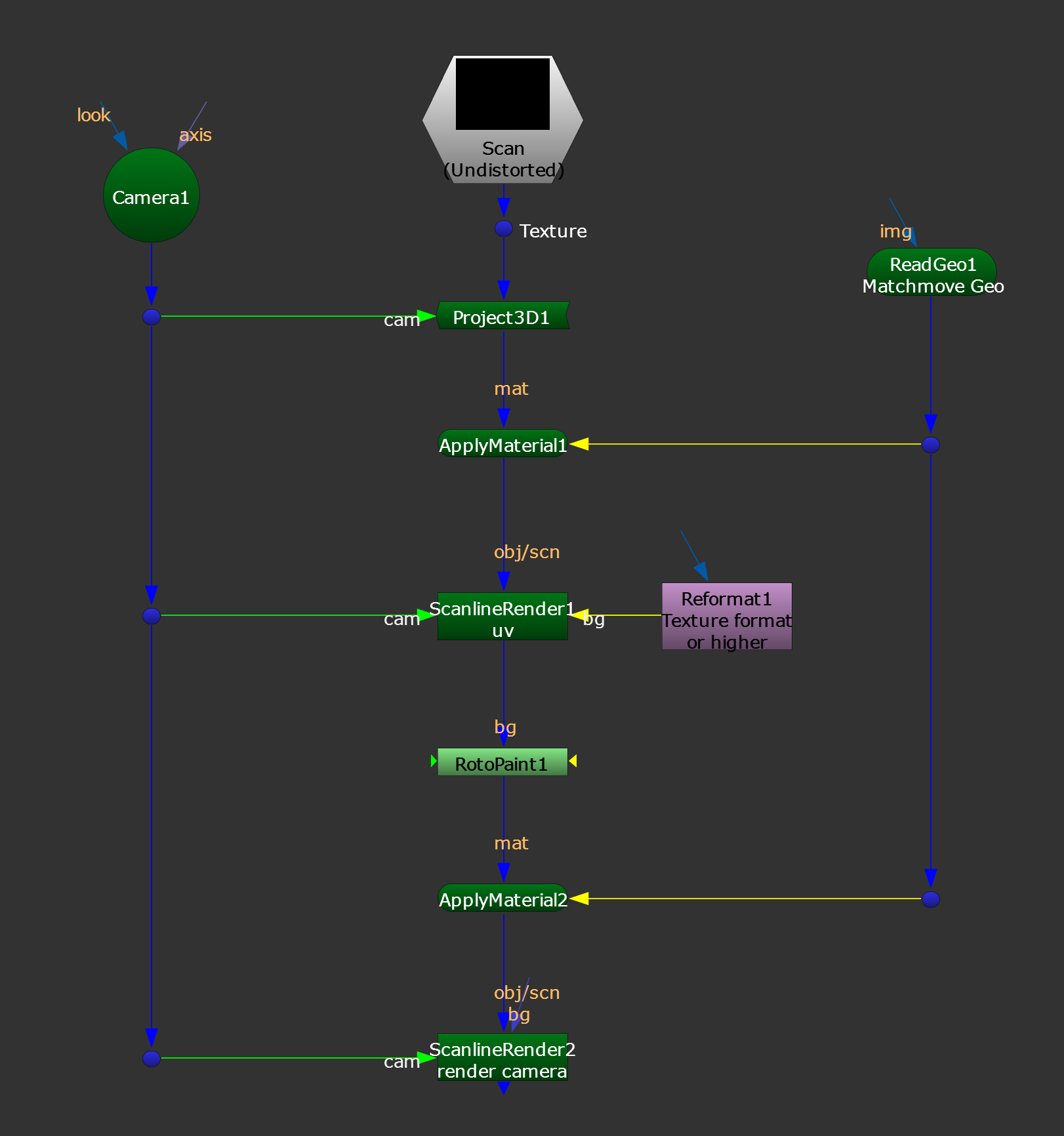
Painting on the UV texture.
I hope you found this tutorial useful. For more Nuke tips & tricks, see Nuke.


