Roto Assisted Tracking In Nuke
How to use rotoscoping to assist with tracking an object…

How to use rotoscoping to assist with tracking an object…
Occluded Tracking Features
Sometimes, it can be tricky to get a track right.
For example, when a screen (to which you want to add a screen insert) gets partially occluded, and you can’t track all four corners of the screen properly to make a CornerPin node.
If you’ve ever tried to guesstimate the position of the occluded corner(s)' tracking point(s) before, for instance, you’ll know how sensitive the CornerPin node is – and how only a slightly wrong offset in a point’s position can squash and stretch the inserted image by quite a bit.
In those cases, you can often use rotoscoping to your advantage. When you roto the screen (feel free to use any working tracks to help animate the points on the spline), you can align the spline with the visible edges and corners of the screen to find the exact location of the hidden corner point(s).

When a screen is partially occluded, for example by a person’s hands, you can often align a roto shape with the visible edges and corners of the screen to find the hidden corners. (The image has been exposed down to see the roto shape better).
And, once you’ve got animated roto points for all four corners, you can either link them to, or convert them to, tracks in a Tracker node:
Link Method
To link a point on a spline directly to a track, first create a Tracker node.
In the Tracker node’s properties, create as many tracks as you would like to link up. (For example four tracks, one for each corner of a screen).
In the Viewer, select the roto point that you want to link to a track. Right-click on the point, and select copy → single point link.
Next, select a track in the Tracker node. Right-click on it, and then select Paste → Paste Absolute.
Do the same for the other tracks – linking them up to their respective roto points – and you’ll end up with a complete track for the screen/object.
Note that you'll have to bake the expressions in the tracks in the Tracker node down into keyframes to populate the Transform tab of the Tracker with keyframes, and use the Tracker like you normally would:
Select all of your tracks, then right-click → Edit → Generate. Select your frame range in the Generate keys pop-up window, and hit OK. Then, change the transform drop-down menu in the Transform tab of the Tracker from none to for example match-move, and all of the keyframe information will show up.
Let’s break down how the linking expressions work under the hood by doing the process manually:
Create a fresh Tracker node again, and in its properties create as many tracks as you would like to link up.
Then, for each track, right-click it and select Edit expressions.
In the Expression Editor window that pops up, add the following lines to their respective tracks:
Roto1.curves.Layer1.Bezier1.curve.0.main.x
Roto1.curves.Layer1.Bezier1.curve.0.main.y
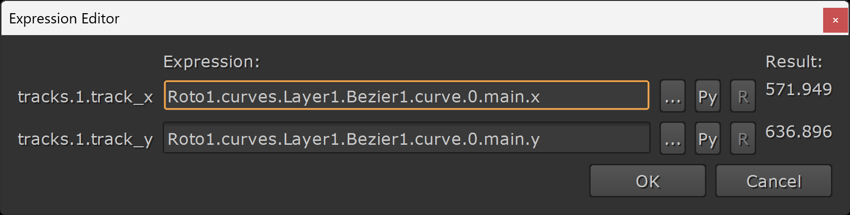
Example expression; linking track 1 of a Tracker node to point number 0 of the Roto1 node’s Bezier1 spline, which is grouped under Layer1.
First, replace Roto1 with the name of your Roto node.
Then, replace Layer1 with the name of the layer that your roto spline is grouped in.
If your roto spline is placed directly in the Root layer (i.e. under no further layers), you can just delete .Layer1, i.e.:
Roto1.curves.Bezier1.curve.0.main.x
– Or, if you have multiple nested layers, keep adding the layer names (from top to bottom in the hierarchy) with a dot (.) separating each, for example:
Roto1.curves.Arm.Hand.IndexFinger.Bezier1.curve.0.main.x
Next, replace Bezier1 with the name of your roto spline.
Then, replace 0 with the number of the point on the spline that you want to track. You can find the number by clicking on the toolbar_label_points button in the roto menu in the Viewer:

Enabling the labelling of points on a spline in the Viewer.
Next, the word main in the expression above refers to the main point on the spline. But you could even use a point on the feathered roto edge, or on the bezier handle, as a track.
If you select a point on your roto spline in the Viewer, and right-click → add expression, you can see on the left hand side what its various parameters are called:
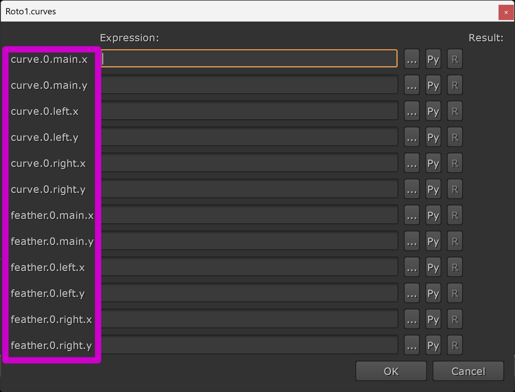
The parameter names of one point (point number 0) on a spline.
Swap the name of whichever point you prefer into the expression we saw earlier to get a track for that particular point.
Finally, x and y just stand for the x and y position, so put them in the x and y track position expressions, respectively.
Convert Method
To simplify and automate the whole process, and have it work when you've got additional tracking/transformation data applied to your roto splines (for example, roto imported from Mocha or Silhouette), you can use a Python script such as this one:
Tip: If you don’t want to install the script, you can make a tool in Nuke instead (and save it as a ToolSet):
First, copy the main python code from here:
Then, create a NoOp node in Nuke, and right-click in its properties → Manage User Knobs.
Add a Python Script Button, and paste the code into the Script section. Name and label the script what you like, for example bakeRotoToTracker and Bake Roto To Tracker, and hit OK.
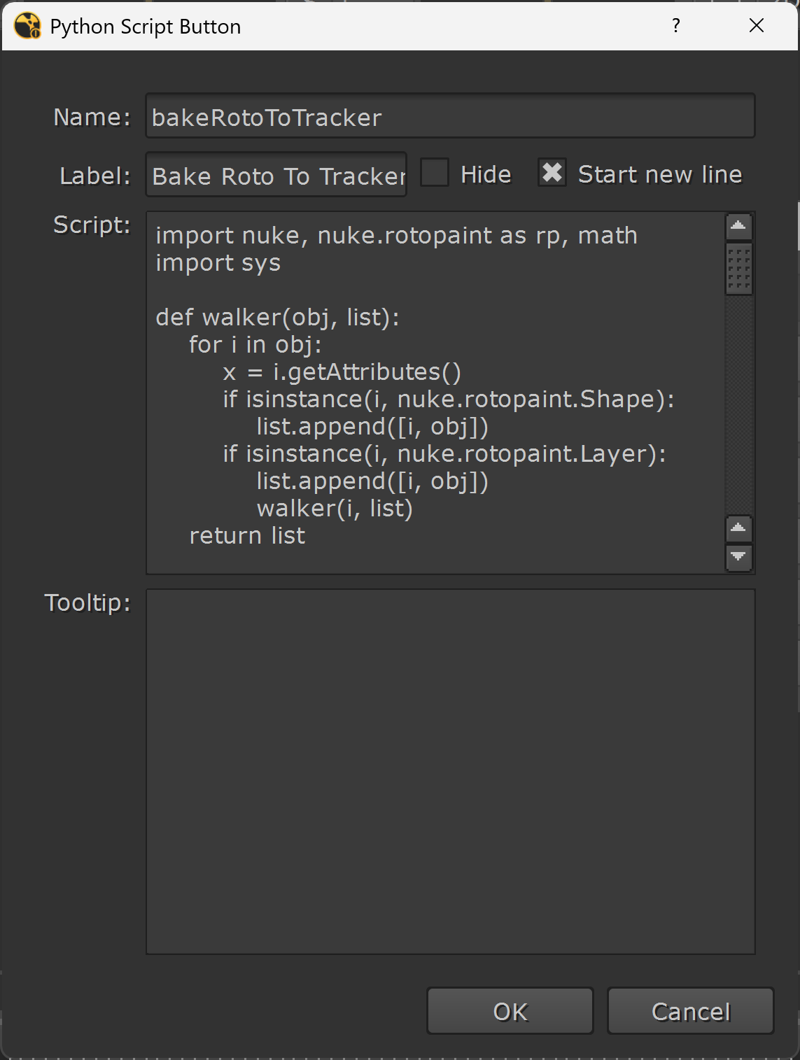
Adding the Python script to a button in a node in Nuke.
Now, you’ll have a tool with a button in it which will run that Python script. Select the Roto node you want to convert, and then hit the button in the tool to convert the spline points to tracks.
In a few seconds (depending on how many points you’re creating tracks for, and the length of the shot), the tool will create a Tracker node containing all the tracks.
To complete the screen insert example, you’ll then have a four point track – ready to export a CornerPin node for tracking in the screen insert.
You can also use the methods above to get free tracks when roto has already been completed for a shot. For example, if you’ve got access to the splines from the Roto department for the shot, you can use those to create tracking data and save yourself some work.
I hope you found this tutorial useful. For more Nuke tips & tricks, see Nuke.


