Best Practices For Compositing In Nuke
Practical tips for improving your compositing in Nuke, and becoming a better team player in the process…

Practical tips for improving your compositing in Nuke, and becoming a better team player in the process…
Have you ever made – or had to pick up from another artist – a Nuke script that looks like this?
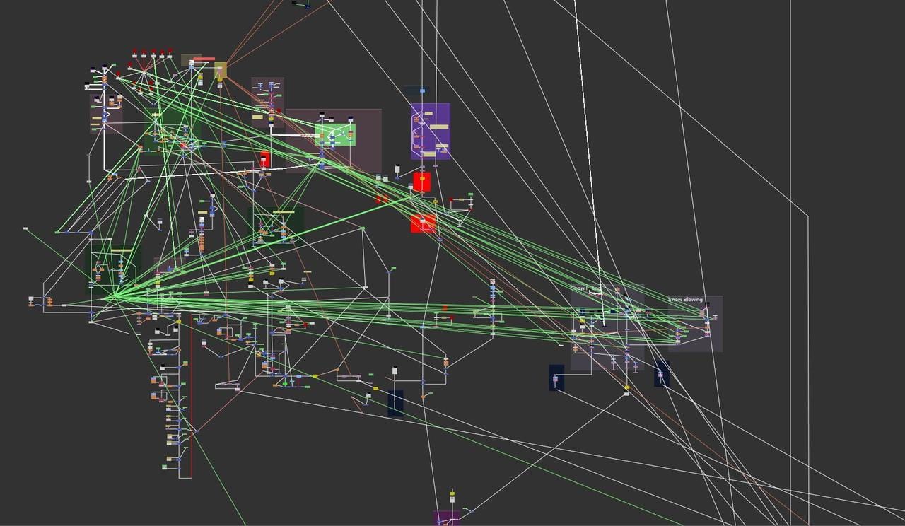
A creative mess.
This guide is about how to avoid finding yourself (and others) in a situation like in the picture above, and reaping the many benefits of doing so.
If you follow these guidelines, I can pretty much guarantee that you'll objectively become a better compositor.
Adopting Good Habits
I’d like to start off with a useful mindset that I think will serve you well.
It certainly has for me.
It’s the idea that if you set yourself some solid organisational ground rules, and get into the habit of following them automatically, you will quickly become:
- Vastly more efficient.
- Much less prone to error.
- A significantly better team player.
You’ll find that increased speed is one of the key long-term benefits. As Benjamin Franklin said:
“For every minute spent in organizing, an hour is earned.”
Let’s look at some ways you can apply this to your compositing:
Managing Your Nuke Script
The structure of your Nuke script will affect your performance as a compositor.
A script like the one we saw above will not be easy to manage or troubleshoot, especially for other compositors picking it up. And it will very likely neither run nor render at optimal performance.
So let’s look at a better alternative.
When it comes to script structure, Nuke lends itself very well to the vertical top-to-bottom style of compositing – as evidenced by the design of its quintessential Merge node:
The Merge node's B-input is the chief input in the hierarchy. If you disable the Merge node, it will pass through the B-input downstream.
And, just by how the pipes are positioned on the node, the A-input and mask-input naturally feed into the Merge node from the left and right, respectively, while the B-input and the output naturally become vertical.
Compositing downwards makes a lot of sense as you inherently won't overlap pipes or hinder access to any of the Merge node's inputs. Compositing with your spine going from left to right will block the mask input with the outgoing pipe, for example.
While compositing in any direction that you want is valid in the sense that it works, I would argue that vertical compositing is the more efficient and cleaner approach.
And, like mentioned above, with only a few simple organisational ground rules we can make a predictable and powerful script structure that is easy to work with.
I would suggest three ground rules:
Rule #1: Keep A Straight Spine
Keep one main vertical spine of B-pipes in your composite that all else feeds into.
Any CG, FX, elements, etc. that you add to your composite become A-inputs coming from the left and merging into this B-spine.
At the top of the B-spine, you place what will be the background of your composite. Going down the spine, each A-input is layered in from the background layers at the top, through to the midground layers in the centre, and down to the foreground layers towards the bottom of your script. (Exactly inverted to how you would stack layers in Photoshop or After Effects).
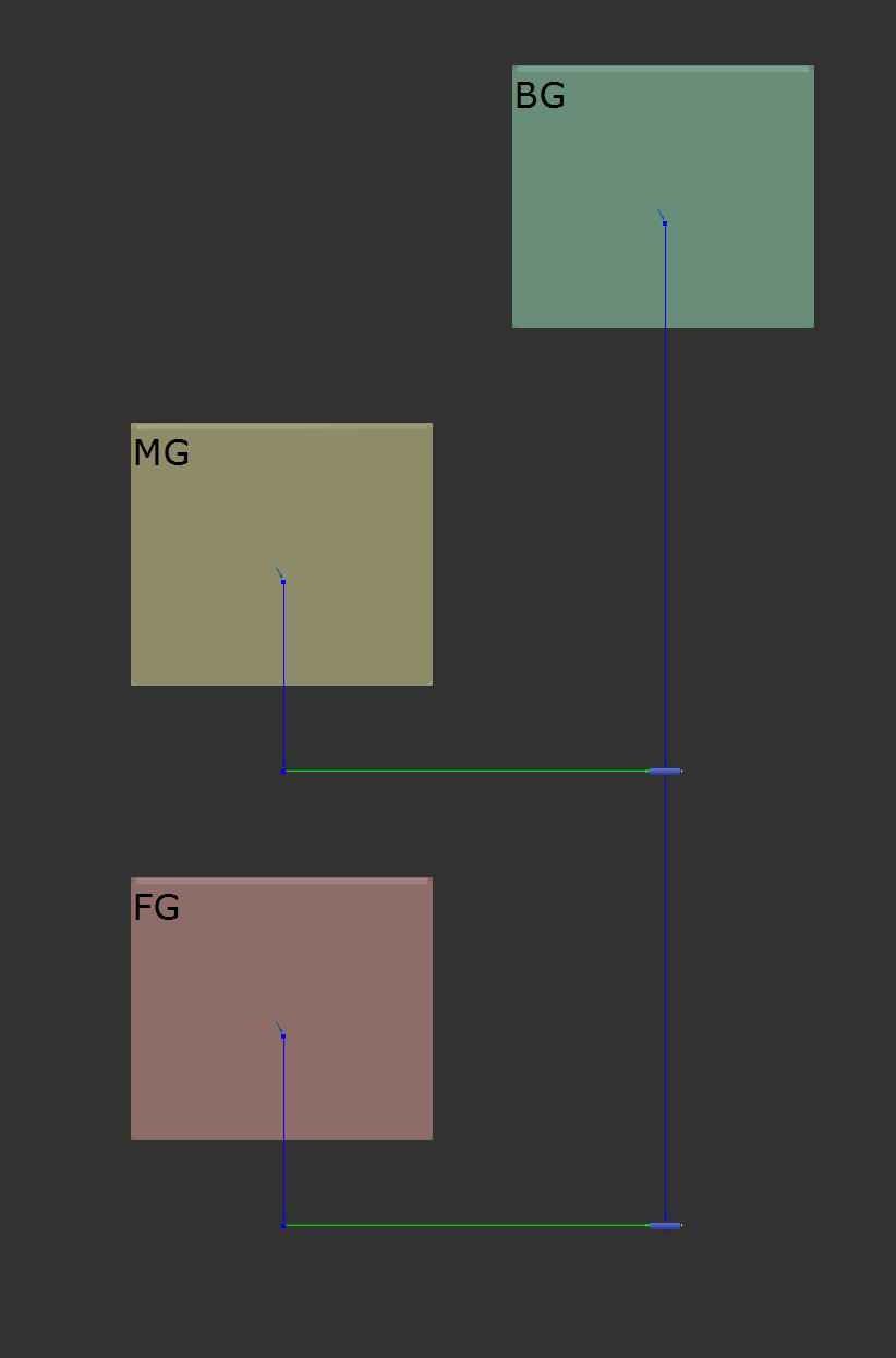
Keeping a B-spine going straight down from the BG, with MG and FG layers merging into it.
Doing it this way will help you layer up your composite in a natural and organised way, avoiding issues with background layers overlapping foreground layers.
You'll also be able to disable any of the Merge nodes in the B-spine and only remove the corresponding A-input from the composite.
This makes it a lot easier to follow your composite step by step and see what gets added where - which is especially useful when you need to make changes to your composite, or troubleshoot the script.
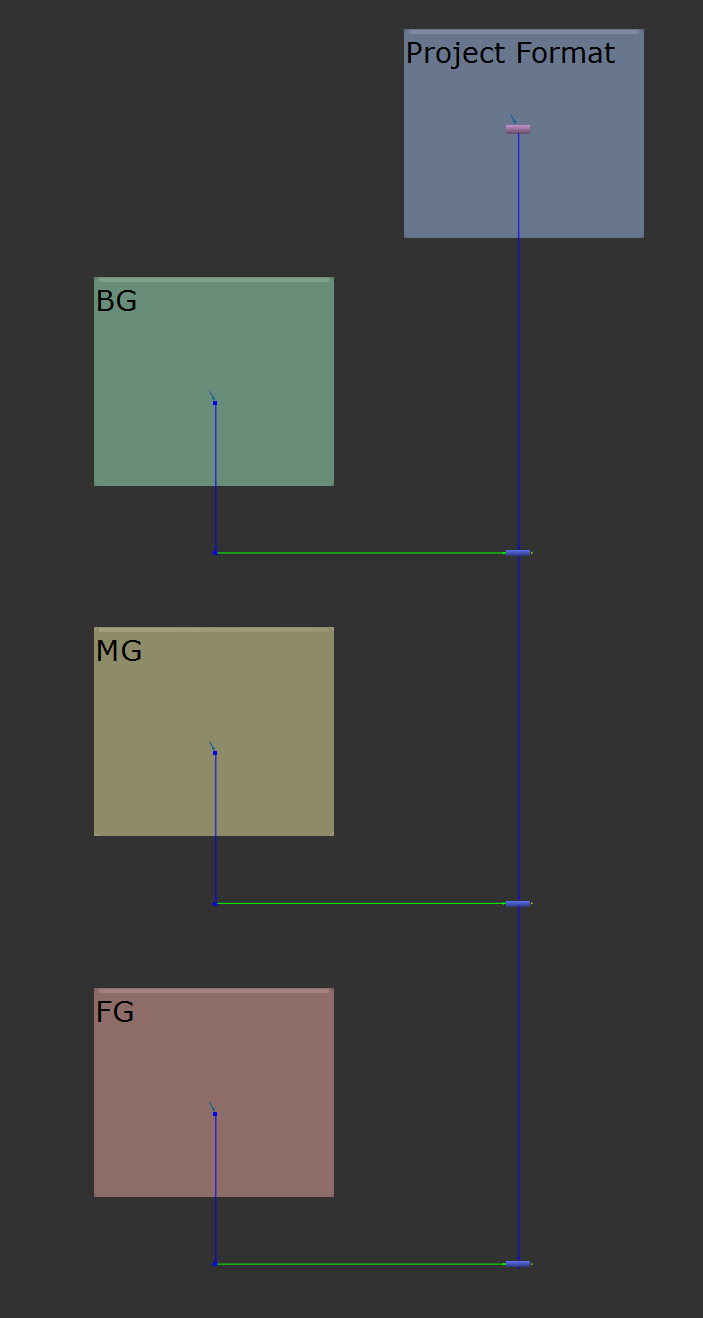
Using a Reformat as the base layer.
Rule #2: Keep Each Section Self-Contained
Think of every part of your composite as a modular unit.
Every A-input in your composite is itself a self-contained mini-composite with its own main B-spine.

Modular sections.
Systematically keeping this modular structure in your script will help you to stay better organised, navigate more easily around the script, and make more well informed compositing choices with less room for error.
Once you get the hang of it, it’ll become second nature and you’ll automatically build your composites in a way that is structurally easy to follow.
This is the goal with every element that you add to your composite. Make individual modules as self-contained sections (that can be precomposited), which become A-inputs to your main B-spine.
Rule #3: Keep Your Script Explicit
Be explicit as opposed to implicit when you build your script.
By that, I mean work in a clear and unambiguous manner, without obscuring the things that you do in the script. Don’t assume that anyone who’s picking up your script will understand what you have done, or why – instead, make it obvious.
It's all about readability - and there are several steps you can take to make your script more easily readable:
↪ Label Your Work
Consistently add a Backdrop node to every A-input section of your script, and label it with a description of what that section is doing.
The description can be a keyword or a short comment, like for example:
- Keying
- Roto Crowd
- Windshield Reflections
Labelling the Backdrops like this is invaluable for easy script navigation and searching.
Remember to change the font size of the Backdrop's label to be sufficiently large – for example to a size of 100. That way, you’ll be able to read the text while zoomed out in larger scripts.
It’s a good idea to set this to be the default font size in the Backdrop node, so that you won’t have to change it every time you create a new one:
Normally, you would specify any custom knob defaults with a little bit of code in your menu.py. However, the Backdrop node is an exception to the rule.
When creating a Backdrop node (either through the Toolbar or the Tab menu), it won't trigger the regular nuke.createNode command (which grabs knob defaults from the menu.py), but will instead call the autobackdrop function of the nukescripts module.
This function lives in a Python script which is saved in the nukescripts folder where you installed Nuke. On Windows, for example, it would be in:
C:\Program Files\Nuke15.1v2\plugins\nukescripts
(Replace C:\Program Files\ with the hard drive and the folder where you installed Nuke, and 15.1v2 with your Nuke’s version number).
Open up the autobackdrop.py script in a text editor, and near the bottom of the script, change the line:
note_font_size=42,
to:
note_font_size=100,
Save the file, and then open a fresh Nuke. From now on, anytime you create a Backdrop node, the font size will automatically be set to 100.
Another thing you could change is the Backdrop node’s colour.
Some people prefer monochromatic Backdrops, but I would argue that varying the Backdrop colours makes it easier to distinguish between different sections of your script at a glance, which makes for a more intuitive script navigation.
If you wanted to, you could use predetermined colours for the Backdrops, for each type of section. For instance, always having a green Backdrop for Keying sections.
There are many Backdrop manager tools on Nukepedia that can help with this, for example BackdropManager, or presetBackdrop.
Whichever way works best for you. The important part is that you clearly label your work.
↪ Avoid Hidden Settings
Unless you have to, try to avoid using special settings ‘hidden’ inside a node's property panel – when there is an equivalent node that you can add in the Node Graph instead.
For example, instead of ticking the invert checkbox inside of a Merge or Keyer node's property panel, connect an Invert node in the Node Graph.
Glancing at your script, anyone can then see that you are inverting the mask or key.
Or, instead of premultiplying the roto inside of the Roto node, use a Premult node. It just makes it easier to see what’s going on in the script.
– The output remains the same, but you make the script more readable.
↪ Display Useful Information
Add key information to the labels of the nodes in your script.
For example, you could add the following expression to the labels of your Blur nodes:
[value size]
Or, add this expression to the labels of your Shuffle nodes:
[value in1]
Or, add this to the labels of your Tracker nodes:
Reference Frame: [value reference_frame]
Doing this will show: how much you are blurring by, or which layer you are shuffling into RGBA, or which reference frame you have set in the Tracker node, respectively, directly on the nodes in the Node Graph.
This saves you time, as you won’t have to open up all the properties to see important information. And, it lets you quickly spot if the values are (not) what they’re supposed to be.
You can set the above as defaults in your menu.py, by adding the lines:
import nuke #(←If you don’t have this line already)
nuke.knobDefault('Blur.label', "[value size]")
nuke.knobDefault('Shuffle2.label', "[value in1]")
nuke.knobDefault('Tracker4.label', "Reference Frame: [value reference_frame]")
↪ Show What You’re Merging
Each A-input should be the same format as your composite, so that when you view it, it’s directly representative of what’s being added to the B-pipe.
If you are using for example a 2D smoke element with a different format, set it to the format of your composite:
Add a Reformat node to the element, set the output format to the project format, set the resize type to None, and untick the center checkbox.
When transforming the element around, instead of just seeing a bounding box outside of the smaller format – and not what’s actually going on – the reformatting will make your A-input properly viewable in the project format as a standalone section.
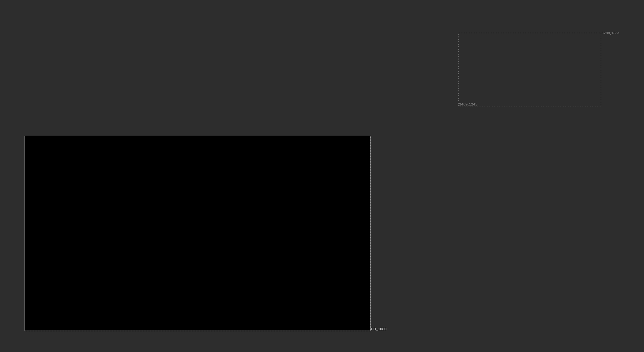
Transforming an element with a different format into place without reformatting it to the project format means that it can be hard to see the output properly.
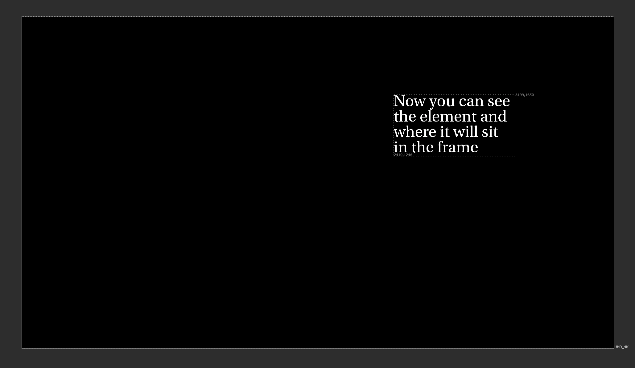
Reformatting the same element to the project format instead means that you can tell what’s going to be merged, and where.
Also, ideally do any masking on the A-pipe instead of using the mask-input on the Merge node. That way, you’ll be able to see the final product of the A-pipe before merging it with the B-pipe.
Using the mask-input on the Merge node can lead to confusion:
With a setup like the one below (left), viewing the A-input doesn’t give us a representative indication of what’s being merged (right).
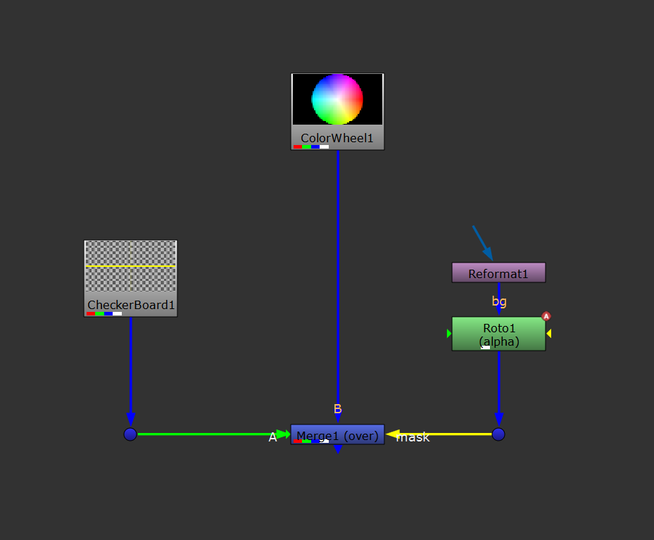
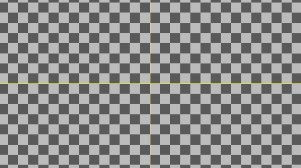
Masking on the Merge node.
You wouldn’t be able to guess that the image below is the result of the merge, just by looking at the A-pipe.
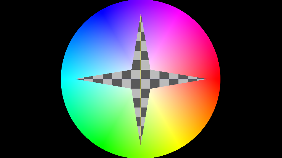
The result of the merge.
However, with a setup like the one below (left), viewing the A-input gives us a much more representative indication of what’s being merged (right).
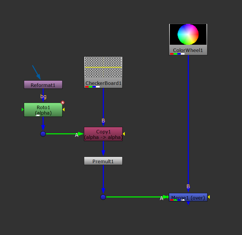
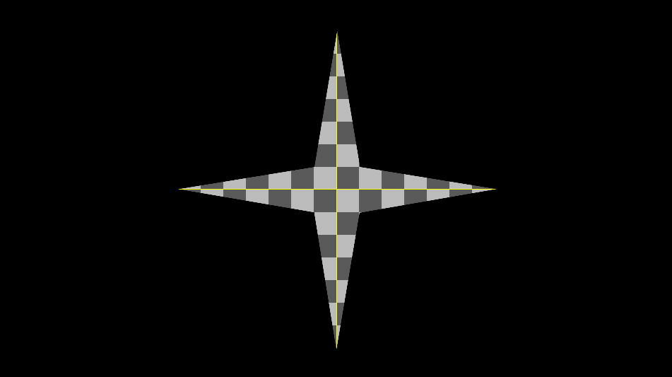
Masking on the A-side.
↪ Make Room
Give the nodes in your script air to breathe.
Space the nodes out so that it becomes easier to add extra nodes in between, or to make changes to a section. You’ll have more room to organise pipes, and the script will become easier to read.
With a bit of extra space, you’ll also be less likely to mis-connect nodes.
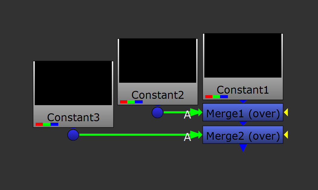
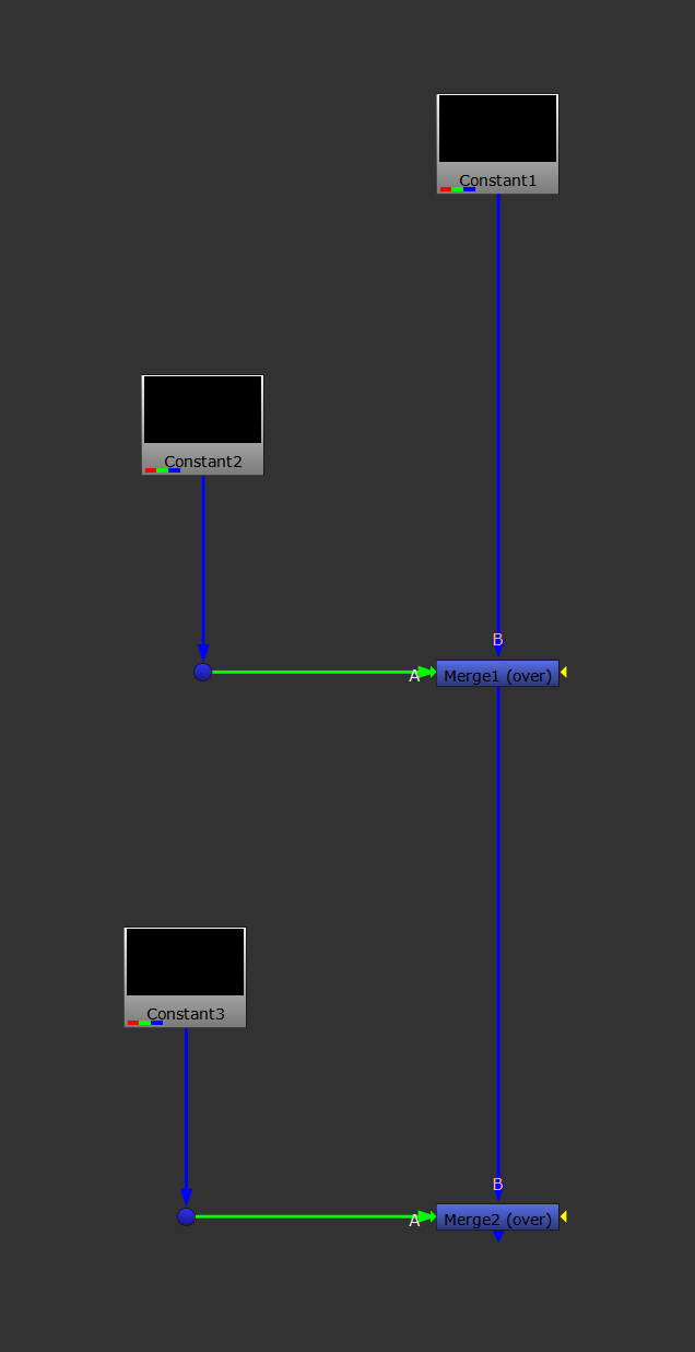
Cramped nodes (left) versus spaced out nodes (right).
↪ Do Not Hide Inputs
Do not use, or use very sparingly, hidden inputs.
Hiding inputs does not ultimately make your script any cleaner. Quite the opposite.
It can cause confusion and accidental connections, and it can make you forget to update important parts of your script.
Even with every pipe visible you can still organise them in a readable way using Dot nodes.
↪ Dot - Dot - Dot
Use Dot nodes generously!
They are great for keeping your script organised. Avoid having pipes criss-crossing over your nodes, and make it clear where an input is coming from.
Angling the pipes 90 degrees using Dot nodes also makes your script look tidier compared to having diagonal lines.
You can even use Dot nodes to indicate which direction a pipe is going.
For example, when you have a horizontal pipe, it’s not always easy to tell at a glance if it’s coming from the left or from the right.
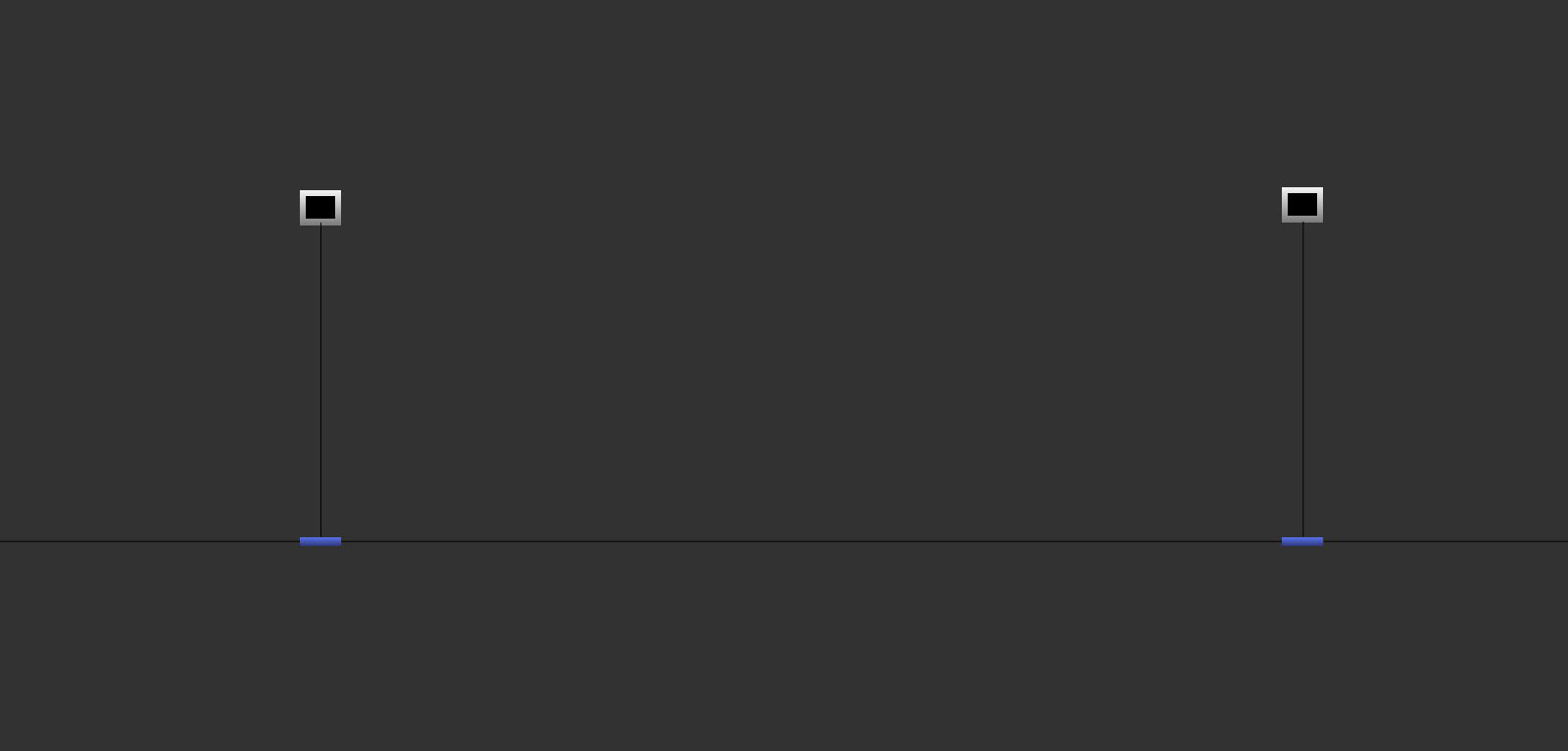
Unclear connections – which pipe is going where?
To help, add a Dot node to the pipe below the last node, just before the pipe goes horizontal, and (in larger scripts) a couple of Dot nodes to the pipe before it goes into the next node.
That way, you make a visual ‘staircase step’ that’s going down into the direction the pipe is headed.
– Visually following the rule of your script flowing downwards.
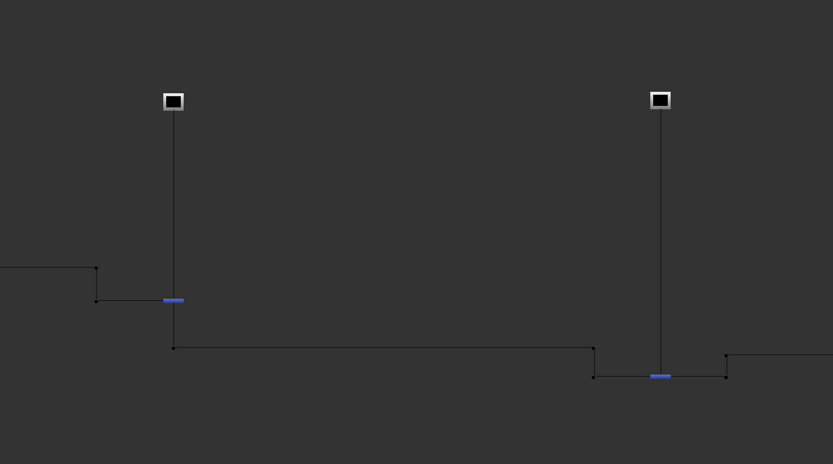
Stair casing using Dot nodes, making the connections clearer. The pipes flow down, with A-inputs coming in from the left, and mask-inputs coming in front the right.
↪ Dot (A) - Dot (B) - Dot (C)
In large scripts, label the Dot nodes.
If you for example have a Camera pipe, a Building Geometry pipe, a Roto Holdout pipe, or any other pipes that lead into several areas of your script, add Camera, Building Geometry, Roto Holdout, etc. to the labels of the Dot nodes in those pipes.
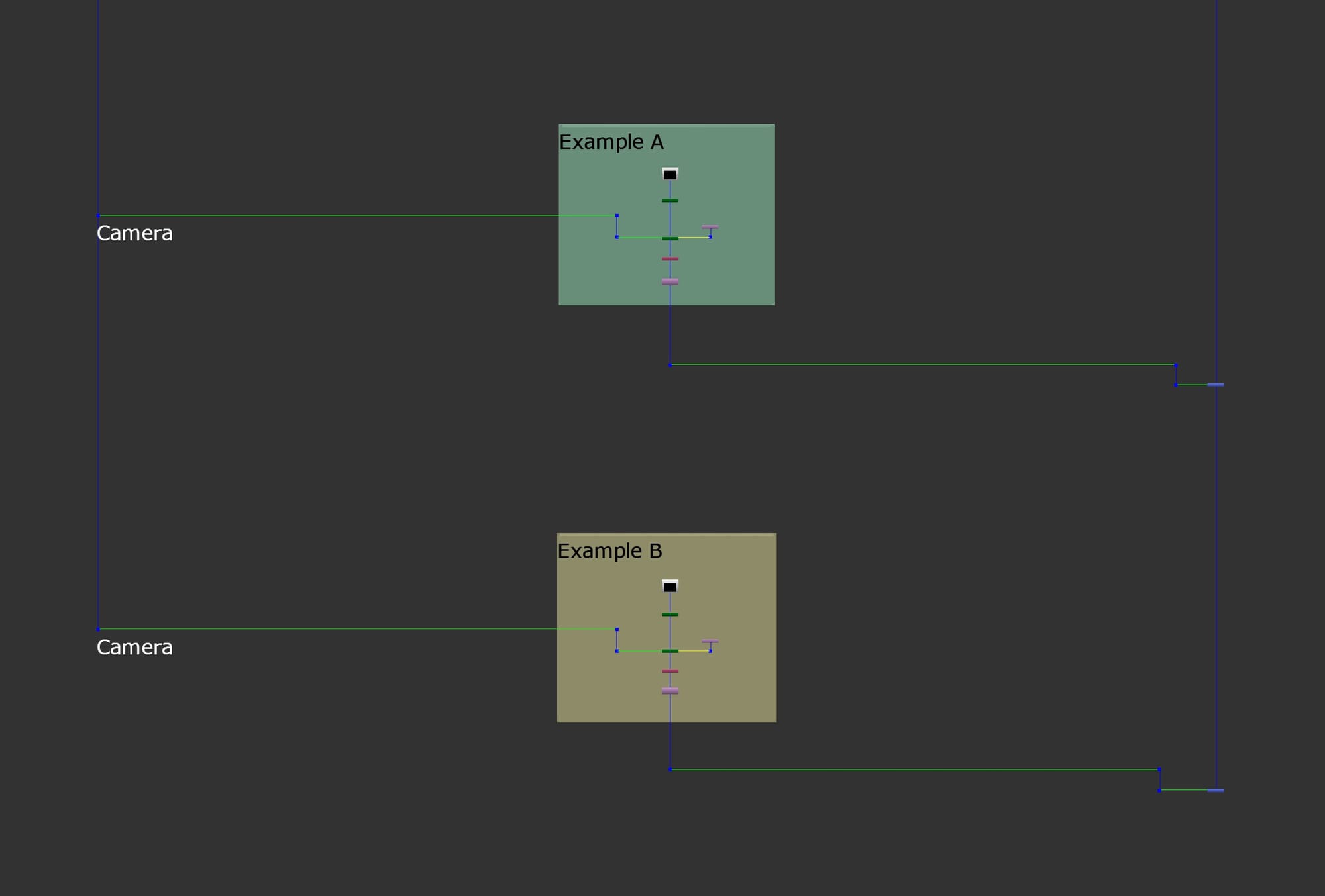
Labelling the Dot nodes in the pipe leading back to the camera.
That way, you’ll only have to trace back to the first joint to find out which pipe is what, instead of all the way back up the node tree to the source.
Remember to set the font size of the Dot's label to be sufficiently large, for example to a size of 100. That way, you’ll be able to read the text while zoomed out in larger scripts.
You can set this to be the default in your menu.py, by adding the line:
nuke.knobDefault('Dot.note_font_size', "100")
↪ Sort Your Nodes
For each section of your script, try to place similar nodes/tasks in the same areas.
For example, try to do all of your grading in one area so that if you need to change the grade, it’s all there in one place. That way, you won’t have to search all over to find what you need.
Also, chaining transformations has the added bonus of concatenation (which we’ll also look at later).
↪ Lock In The Format
When you create a node in Nuke, it will typically take the format of whatever it's connected to as its input format.
However, if the node is not connected to anything, it will typically take the root.format, i.e. the current project format, as its input format.
That’s usually great within the confines of one specific project, but if you want to copy a setup from one project to another, or make a ToolSet or gizmo, you may find that it can mess things up.
When looking at the output of a setup in a different project format, you’ll find that roto shapes, projections, etc. can become misaligned, and the whole result can break apart.
And if a setup you saved as a ToolSet on some past project breaks on your current project, it can be tricky to realign everything unless you remember exactly what the old format was.
When you create tools or setups, it’s obviously best to be format agnostic and set them up in such a way that they can accommodate any format. However, that’s not always practical.
But I would at the very least recommend to lock in the format so that everything is self-contained and will still line up with itself in another project. That way, it’ll be much easier to adjust the setup to work for the new project.
Locking in the format requires a little bit of extra effort, but I believe it’s worth it because you’re helping your future self and others a great deal.
– Which is why I adopted the following practices into my everyday compositing:
Plug a Reformat node, with the output format knob explicitly set to the current project format, into any relevant nodes that don’t have their input connected to anything.
Do this for unconnected Roto nodes, Noise nodes, ScanlineRender nodes, and any other nodes or gizmos that take a format as an input.
Also, change any format knobs in a node’s properties to the specific project format, instead of just root.format (which is typically the default).
Do this for Constant nodes, Checkerboard nodes, Reformat nodes, and any other nodes or gizmos with a format knob.
While it does take a few extra seconds to do this every time you make those nodes, you’ll thank yourself later on – when you inevitably go back and dig up a great setup that you once made, which is perfect for a new project.
↪ Clear Out The Clutter
As you composite along, and especially when you version up a script, delete the nodes that you no longer use.
Often, you’ll test something out, or swap in a different node setup to address a note, and end up leaving a bunch of nodes disconnected off to the side, or disabled in your stream.
Once you publish a new version and/or version up your script, delete all of those unused nodes.
Tidying up along the way will keep your script from becoming bloated. It will be easier to navigate, take up less RAM and storage space, and run more efficiently.
It’s Not Just A Pretty Face
There are several reasons for why the three ground rules above are important to follow:
Other compositors will often have to open up and work with your scripts, and the easier it is for them to hit the ground running, the better.
As mentioned before, you might even have to come back to the script yourself after an extended period of time, and the same applies.
I would argue that it’s disrespectful to your colleagues, not to mention counterproductive, to leave them a messy script:
“Clutter is nothing more than postponed decisions.”
– Barbara Hemphill
Passing on messy scripts forces your lack of decision making onto others, creating more work and frustration.
Not only that, keeping your scripts organised literally saves money. You’ll make fewer mistakes, and have a much easier time troubleshooting in an effective way when you do.
Which means you’ll spend less time doing unnecessary work.
Avoiding Duplicates
If you’re merging together the outputs of for example five pipes, avoid having duplicates of the same five Defocus nodes or other nodes in each pipe.
Instead, merge the pipes together and then do one Defocus, or one instance of a node setup.
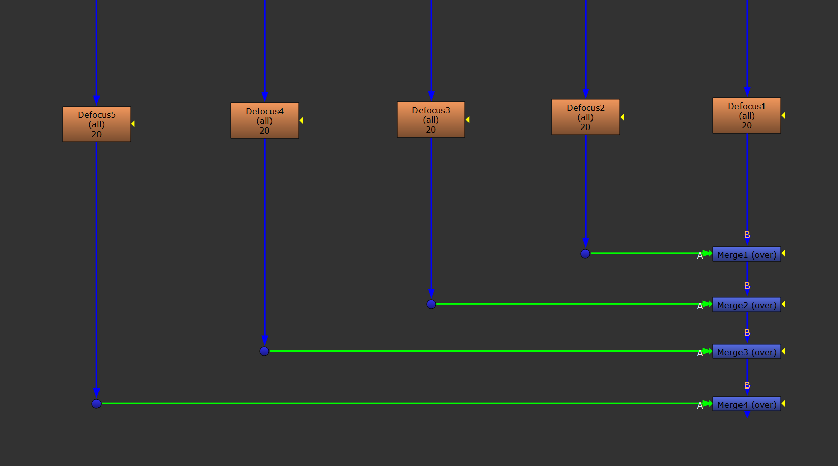
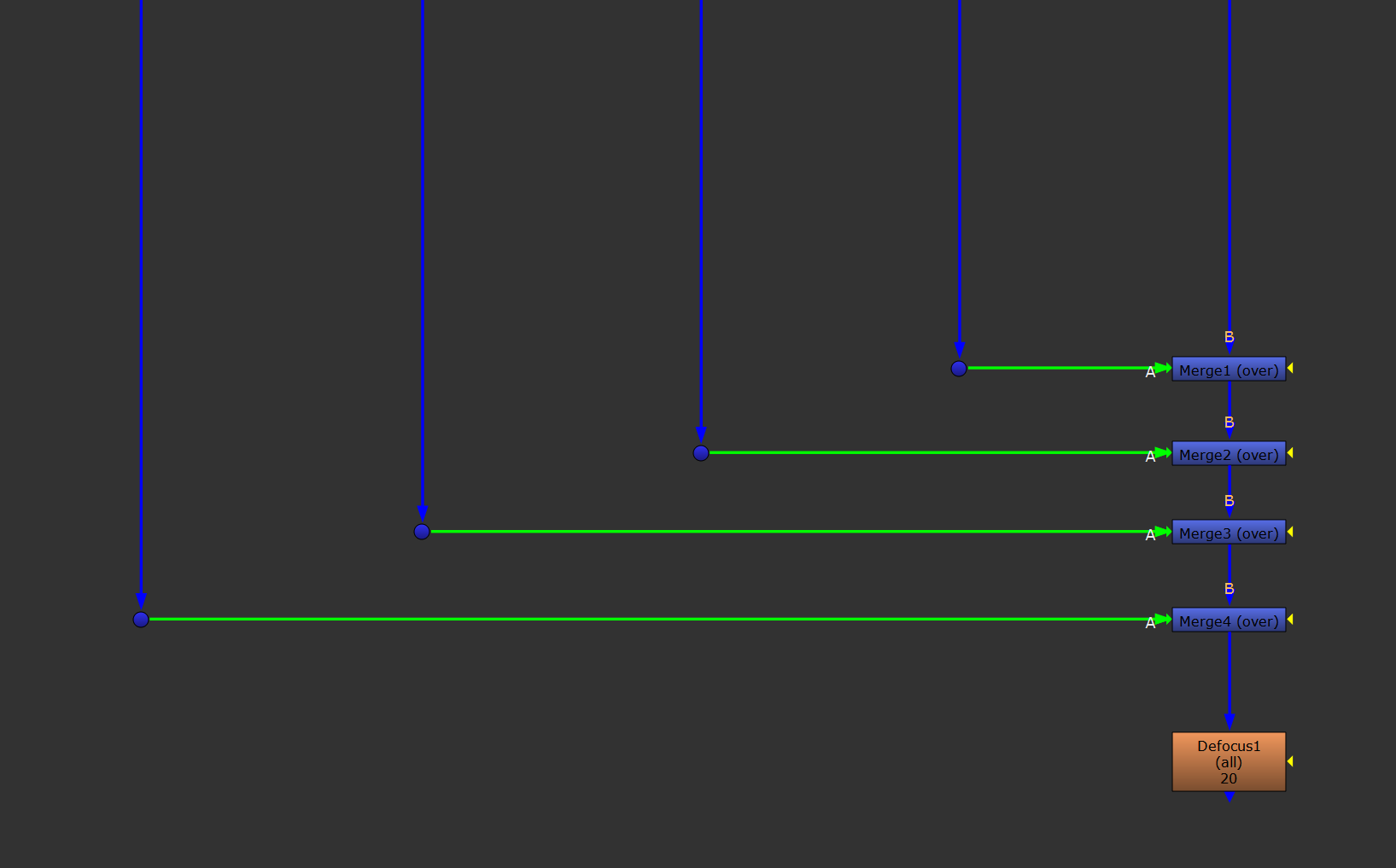
Poor efficiency (left) improved by consolidating the duplicates (right).
This will speed up your script’s processing time by a lot, since you reduce the number of nodes that need to be calculated.
Speaking of duplicates:
Referencing One Source
You’ll often find that you need to use a specific source in your script multiple times.
It could be a scan, a camera, some geometry, a matte, or anything else.
Instead of duplicating the source every time you need it in your script, make a habit of using only the one, and then organise pipes leading from it to the areas in your script where it’s needed.
This centralised approach is beneficial because:
- If a source needs to be updated, you only need to update it once in the script. You can’t forget to update any duplicates when there are none.
- Your script will run faster. Instead of loading and buffering multiple copies of a source, Nuke only needs to do it once.
This also applies to expression linking nodes:
Instead of making multiple copies of a Tracker node, make use of its expression linking function and create linked Transform nodes.
These can then be duplicated around while still referencing the one central source.
Optimal Layering
Like we saw in Rule #1: Keep A Straight Spine, you should ideally layer your composite with the background layers at the top of the script (i.e. the equivalent of the bottom layer in Photoshop), then the midground layers in the centre, and finally the foreground layers at the bottom (i.e. the top layer in Photoshop).
This also applies when inserting something into the scan, in between foreground and background subjects and objects in the scan. Which means, you’ll have to separate out those layers from the scan to treat them independently.
To explain what I mean, let’s say that you’re putting a CG car in the street behind a foreground person on the pavement.
Many compositors will use the roto matte of the foreground person to stencil out the CG, before merging the stencilled out CG on top of the scan.
– But that’s not a great way of doing it. You would have little to no control over the foreground person’s edges or the edge blending with the new background (the CG car).
And, if the foreground person’s edges were motion blurred, you would see the original background through the motion blurred edges, on top of the CG car.
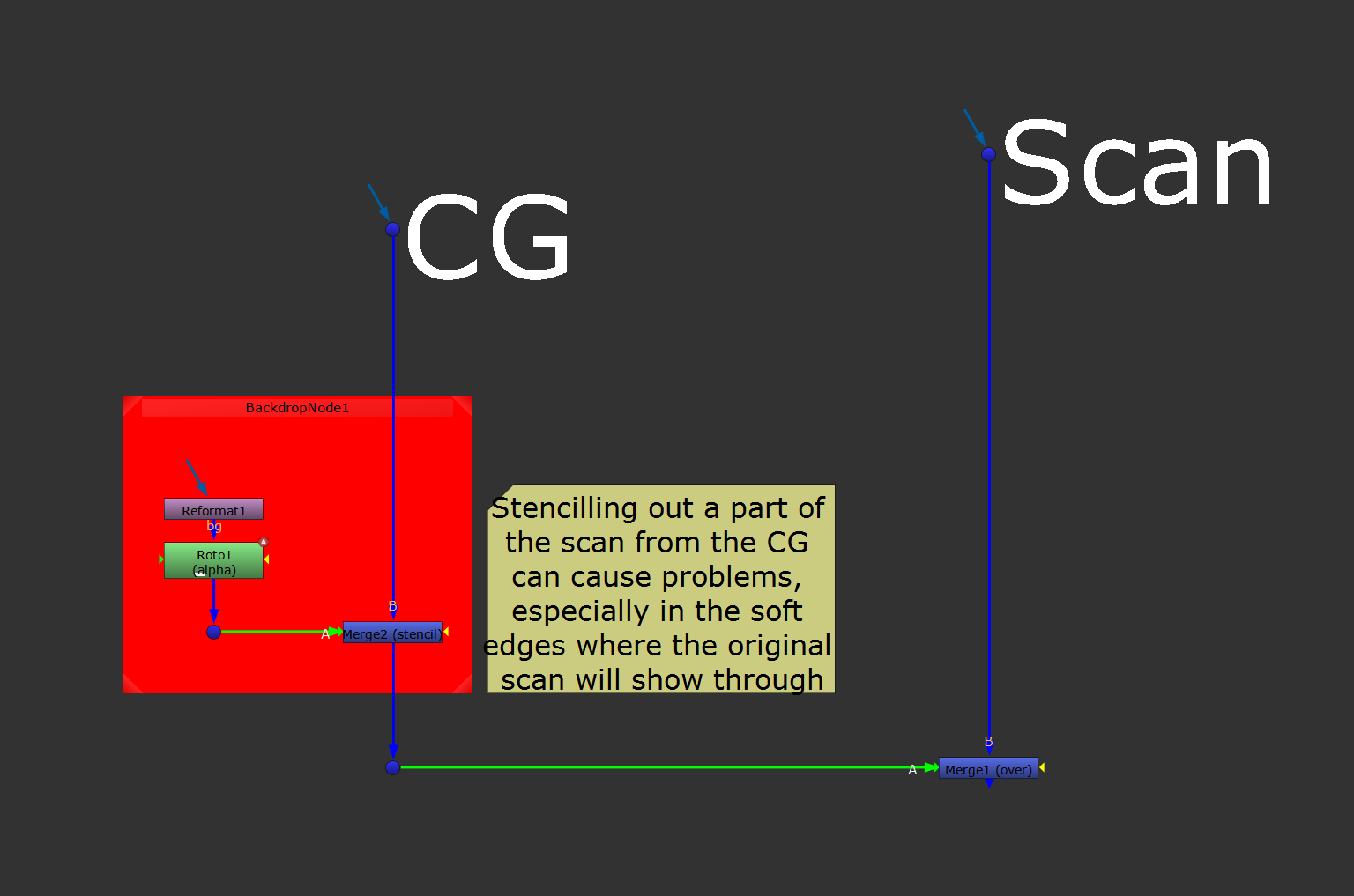
This way of layering the composite can cause problems.
Instead, you should separate out the foreground person and treat that as its own foreground layer.
So – first, merge the CG car directly on top of the original scan.
Then, branch off a separate pipe from the original scan, copy in the roto matte as the alpha, and premultiply.
Next, merge this new foreground layer (that contains just the foreground person) on top of the comp of the CG car and the scan.
Finally, add any lightwrap, edge extension, or edge blending to the foreground layer (before the masking by the CG car in the stream).
Doing it this way means that you’ll have full control over the edges of the foreground person, and how they integrate with the CG car.
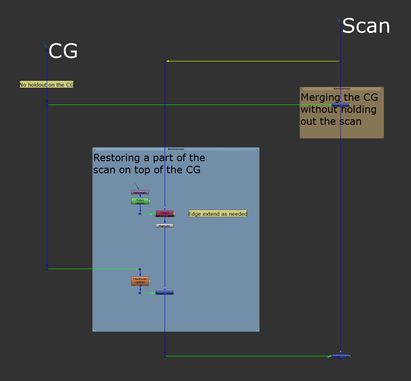
Layering the CG and scan in a way that gives you full control over the edges.
Managing Your Bounding Box
The bounding box tells Nuke which part of the frame it should process.
It’s represented by a dotted-line box in the Viewer. Anything outside of the bounding box will be ignored when Nuke is calculating the image, even if there is actual pixel data there.
Keeping Track Of Your Bounding Box
It’s important to keep an eye on the bounding box in all parts of your node tree to ensure that it doesn’t grow too large, and that you’re not slowing down your script by processing unnecessary pixel data.
And conversely, it’s important to maintain enough of a bounding box to include all of the pixel data you’ll need downstream for your composite.
If you consistently trim your bounding box throughout your composite, your scripts will be more interactive, with faster loading and buffering. They will crash less often, and your rendering times will decrease.
This leads to a productivity boost for you, and less strain on the company's render farm and storage. Win-win.
When the bounding box is larger than the frame, also known as overscan, you should pay special attention to it.
Sometimes you need this overscan, for example when using a Lens Distortion that pulls in pixels from outside of the frame.
But often, the bounding box will tend to grow outside of the frame without you needing it to, simply as a byproduct of everyday compositing. Nodes such as Blur, Defocus, Transform, or (especially) CornerPin can balloon the size of your bounding box and really slow things down.
Other nodes might cause issues if the bounding box is smaller than the frame. Vector-based nodes like the MotionBlur node, for example, can cause artefacts and streaks in the image.
And so, sometimes, you’ll have to increase the bounding box up to the full format, for example with a Crop node.
Controlling The Bounding Box
Luckily, there are many options for controlling your bounding box:
- Use Crop nodes to remove your overscan where you no longer need it. (Or, to increase the bounding box up to the full format, in cases like described above).
- Use the Crop node or the CropPadded (or similar) gizmo to trim your overscan when you only need some of it.
- When you merge your A-input into the B-spine, set the bounding box to B in the Merge node’s properties in order to only keep the overscan from the B-stream. (Assuming you have enough overscan in the B-stream already).
- In the ScanlineRender node's property panel there is an overscan setting for when you need to output overscan. Setting this to 100 will add an overscan of 100 pixels.
- Use the AdjBBox node to add overscan to the input. This node is useful for example when you have a procedural node, such as Noise, and need overscan.
- The CopyBBox node does what it says on the tin; you can use it to copy the bounding box from one input to the other. This can be useful if you want to get the original bounding box back from your CG render after processing it.
- You can use the AutoCrop function in the CurveTool node to crop the bounding box of smaller elements or CG renders.
- The BlackOutside node adds a one pixel black border around your bounding box and can be useful if you want to remove stretching/repeating pixels from the border of your image.
Viewing The Overscan
When you need to work with overscan, it’s useful to be able to see what’s actually there outside of the frame, or project format.
You can right-click in the Viewer and tick show overscan to display the overscan. (You could also open the Viewer settings by pressing S while hovering your mouse over the Viewer window, and then tick show overscan to display the overscan. Here, you can also choose how much overscan to display, by adjusting the overscan setting).
Or, you can branch off a Transform node from your composite and scale it down, if you just need a quick look. For example, to check that nothing has been accidentally cropped upstream.
Keeping The Overscan
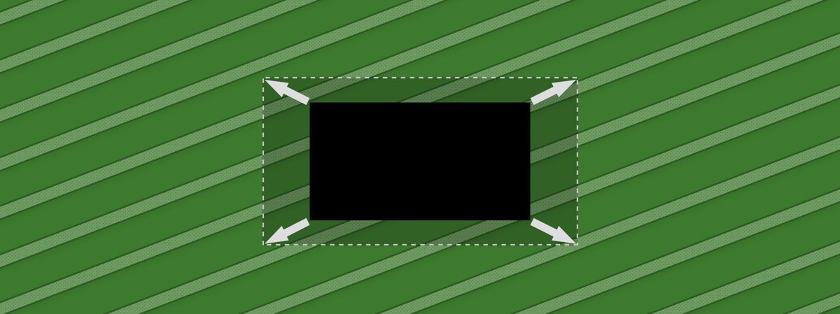
Some nodes and gizmos, like for example Kronos or MotionBlur, automatically crop the bounding box to the input format – without providing any options for processing and keeping the overscan.
Here is a workaround for dealing with those:
Managing The Channels In Your Script
When compositing in Nuke, especially when working with CG renders, it’s likely that you’ll be dealing with numerous render layers and channels in addition to the standard RGBA.
Processing all of these extra layers can get quite heavy and slow down your Nuke script, so let’s go through some best practices that can help speed things up.
Layers Vs. Channels
First, just to clarify, a channel is what carries the image data in Nuke.
A layer is a channel set; a container that can hold multiple channels. All channels must belong to at least one layer, and the channel names always include the layer name as a prefix.
Nuke's default layer, conveniently called rgba, contains the channels rgba.red, rgba.green, rgba.blue, and rgba.alpha. In a typical image this relates directly to the red, green, and blue components, as well as the transparency, of the image.
But you could just as well be working with coordinates in a world position layer which is called for example PositionWorld, where the channels within carry the X, Y, and Z positions in world space: PositionWorld.x, PositionWorld.y, and PositionWorld.z.
Or, a depth layer with only one channel, depth.z, where each pixel value represents the distance to an object from the camera at that pixel's position in the frame.
This is all just to say that channels can represent other numerical data than just the red, green, and blue colour components of an image.
No matter what they contain, however, the channels of a layer will be mapped to red, green, blue, and alpha in the Viewer, in that order.
A motionvector layer with two channels, motionvector.u and motionvector.v, for example, will be mapped to red and green.
So, when the pixel values are positive, the motionvector.u component will look red and the motionvector.v component will look green when viewing the motionvector layer in the Viewer. Which is why this type of layer will often look yellow in the Viewer (mix of red and green).
And why a depth layer with one channel, depth.z, will look red.
Okay, back to working with channels:
Keeping Only The Channels That You Use
To keep your script snappy and rendering quickly, it’s a good idea to actively manage the channels in your script.
Make a habit of using the Remove, Shuffle, and Copy nodes throughout your script in order to only pass through the channels that you need in your stream.
For example, once you have rebuilt your CG beauty you can remove the shading components and/or light groups from the stream.
Using a Remove node with the operation set to keep, you can for example select to only keep rgba, the depth pass, and the motion vector pass. (If you have multiple DI mattes, you can shuffle them back in with a Shuffle node).
When you then apply a ZDefocus or VectorBlur, these heavy nodes will not process multiple unnecessary channels (if the nodes are set to affect all channels - as is the default).
And after you’ve added those heavy nodes, remove the depth and motion vector passes, and only pass through the rgba and any DI mattes.
Doing this will help you avoid ending up with a bloated layer list downstream, which can bog down your script.
Affecting Only The Necessary Channels
Imagine you have a CG render with 30 layers and you connect a Defocus (all) node to it and increase the defocus.
Nuke will then process all of those layers and defocus each channel. If you only actually needed to defocus the RGBA channels, that’s a lot of wasted processing. Not only will that slow down your script, it will also slow down your rendering.
When adding nodes like this, which by default affect all of the channels, make a judgement call if changing the channels setting in the properties panel from all to for example rgba is a better option.
Even when you only keep the channels you use, like advised earlier, there will often be times where affecting them all is unnecessary, or even detrimental.
Visual Channel Indicators
Nuke's interface actually shows you which channels are being processed, in a couple of places.
– Which is useful for keeping track of channels in your composite.
The first place is on the nodes themselves:
Node Decorators
Nodes have coloured rectangular tiles along the bottom edge to indicate which channels or layers are being processed and output.
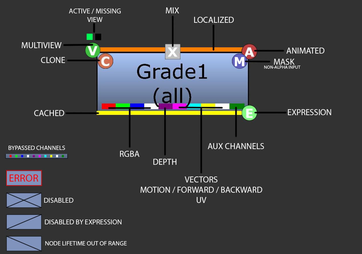
A wide rectangle means that the corresponding channel or layer is being processed by the node, and a slim rectangle means that it’s being passed through untouched.
The colour of the rectangle corresponds to specific channels or layers. Reading from left to right:
- Red: red channel
- Green: green channel
- Blue: blue channel
- White: alpha channel
- Purple: depth
- Pink: motion vectors
- Cyan: forward vectors
- Yellow: backward vectors
- White (again): UVs
- Dark green: auxiliary layers/channels, i.e. any other layers/channels than those listed above.
Viewer List
Additionally, if you look in the lower left corner of the Viewer, there is a list of the currently available channels – at the point in your stream where the Viewer node is connected.

Channel list in the Viewer.
A quick glance here will tell you if you have any superfluous channels in your stream.
Bonus Channels
Some nodes output new channels by default, like the ScanlineRender node which outputs motion vectors and depth.
Sometimes that’s useful, but it’s not always needed. Keep an eye out for unnecessary channels being added to the stream when you composite, by using the indicators mentioned above, and trim them as needed.
Creating Custom Channels
You can create your own custom channels in Nuke.
This is useful for many things, for example when you want to pass a particular matte through your stream without changing the alpha channel.
When separated into a custom layer and channel, the matte will still be affected by your compositing, such as transformations, 3D projections, defocus, lens distortion, etc.
In order to create a custom channel for your matte, you can use for example a Copy node or a Shuffle node.
Copy or shuffle the alpha into a new layer by selecting new in the channel selection drop-down menu.
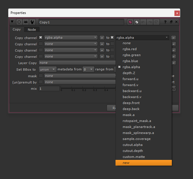
Creating a new layer and channel.
Then, give the layer and channel a name, like so:
layer.channel
– where layer is the layer name and channel is the channel name.
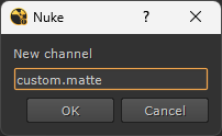
Naming the new layer and channel.
You can name your layers and channels pretty much anything you like, but try to be descriptive;
windows.matte is a good name because it says exactly what it is, in the name. You can be more granular if needed: upperWindows.matte.
Please note:
You’ll have to make sure that any holdouts which you apply to your stream also affect your custom layer (if they should). Because by default, a Merge or ChannelMerge node will only affect rgba.
You can do this by adding a second Merge or ChannelMerge node after the first one and choosing to stencil/mask the custom layer/channel by the holdout matte and outputting the (now held out) custom layer/channel.
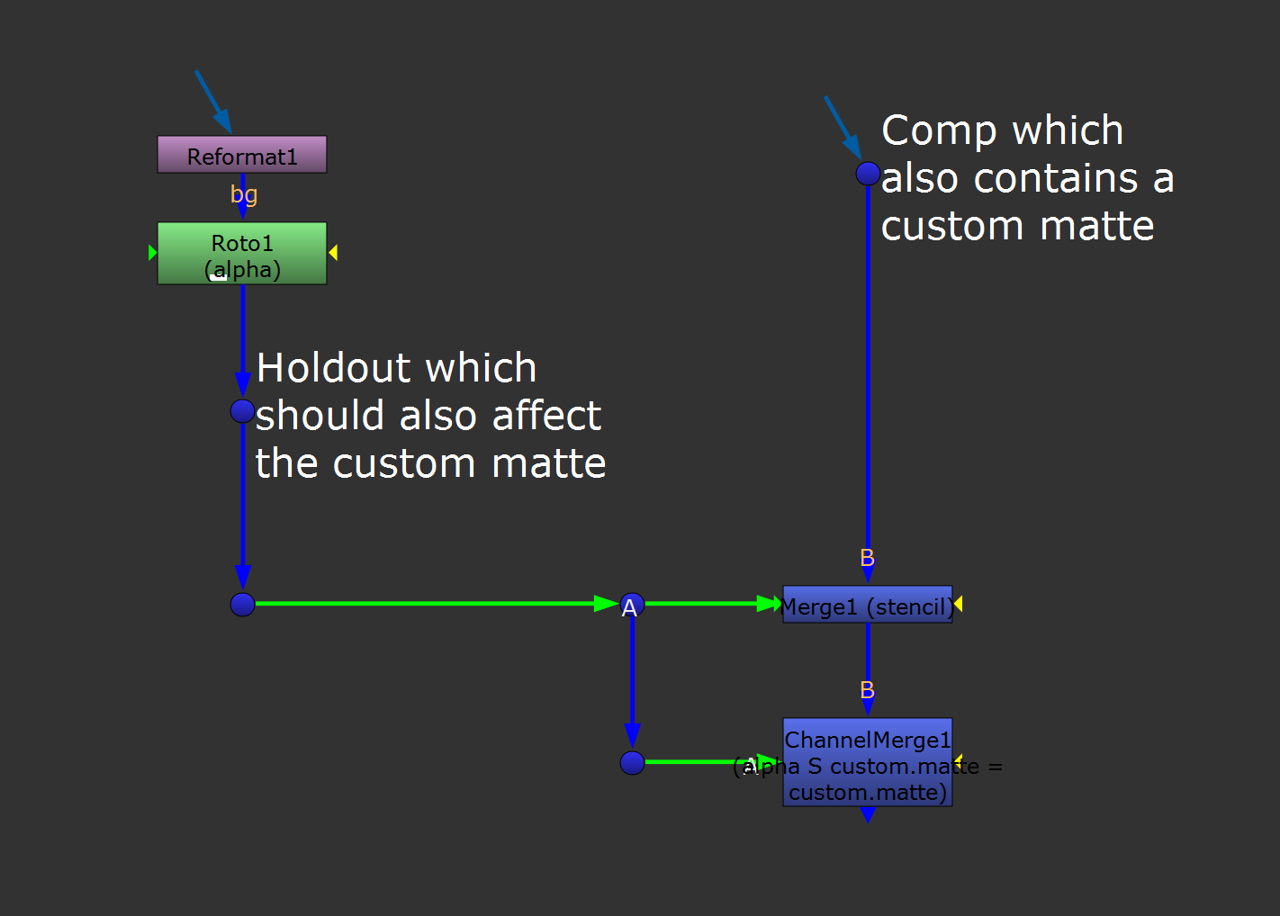
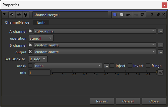
Holding out a custom matte in your stream.
Order Of Operations
When compositing in Nuke, strive to keep the image fidelity intact, and to reduce the risk of breaking your composite with any further changes (e.g. addressing notes).
In order to achieve that, there are several things you can (and should) do:
Concatenating Transformations
Many of the operations that you perform on an image will apply some sort of filtering to it.
Meaning, the output won’t be as sharp as the input - it gets a little bit softer each time.
That’s because when you make a change to a pixel in your image, that change often relies on the surrounding pixels.
If you translate the image 0.5 pixels to the right, for example, Nuke has to 'make up' new pixel values by averaging between the existing ones.
If you’re not careful about the order in which you’re applying these operations, the image will get softer and more pixelated at each step of the way.
That’s where concatenation comes in.
When you perform various transformations to your image, stack the concatenating nodes (list here) one after another, without any non-concatenating nodes in between.
That way, only a single filter hit will be applied to your image, determined by the filtering method that’s set in the properties of the last node in the concatenating stack.
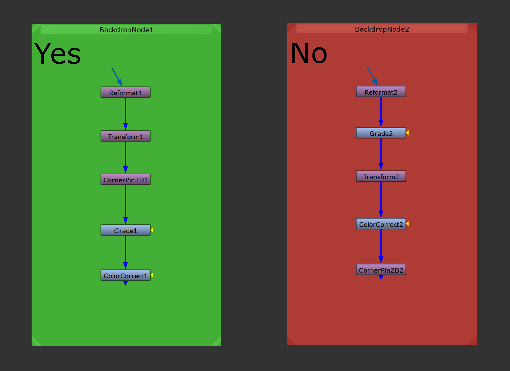
Stack transformation nodes to achieve concatenation.
Reformatting First
Often, you’ll be working with half resolution CG renders, or 2D elements in a different format to your project format.
When you do, always reformat them to the full resolution format before continuing working with them.
That way, you can swap in the full resolution renders later on, and your composite won’t break. All the masking and other work will still line up as expected.
And, you’ll adhere to the Show What You’re Merging rule that we saw earlier.
Masking In The Right Places
Let’s say that you’re compositing a 2D smoke element into your scan, and you mask it behind a building.
If you get a note to move the smoke a little bit higher up in frame, that transformation would need to happen before your masking.
Otherwise, the holdout will follow along and become misaligned with the building.
On the other hand, if you stencilled out something from the element itself, like a part of a smoke machine that got caught in the key, the aforementioned transformation would need to happen after that particular mask.
Otherwise, your mask would no longer line up to cut out the smoke machine.
So it’s important to account for transformation changes both ways.
When you are compositing a 2D element with your scan, and holding out a part of the scan from the 2D element, any masking that you do should go after these operations on the element:
- Transformation
- Reformat
- Defocus
- Motion blur
- Lens distortion
Grading In The Right Order
When doing grading work to match up for example a CG render, matte painting, or element to your scan, the order of the grading matters.
Once you match the black levels, avoid doing any more grading work downstream. Otherwise, you can accidentally mess up your black levels.
Preparing For Likely Changes
When building your composite, structure it in a way that lets you make changes easily without having to redo large sections of your script.
Masking In The Right Places, which we saw earlier, is a great example of that. But also, anything else that is likely to change should be standardised so that the comp won't break by the change.
For example, when making a template script for a sequence of similar shots, try to avoid doing bespoke 2D matchmoving and roto work. Instead, build a more flexible setup with Cards and a Camera.
When copying the setup across to another script, you’ll then be able to swap out just the camera, and have it all line up correctly.
Similarly, when grading CG renders, use Cryptomattes and Position mattes instead of manually rotoscoping masks.
Regraining Once
Avoid regraining each element of your composite individually.
That would require a lot of grain nodes, and slow down your script.
Instead, build up a combined grain matte (for example in the B-pipe’s alpha channel), and use it to regrain all of the elements in one go at the end – using one grain node.
Keeping Track Of Geometry
Quick tip: Disable or remove any ReadGeo nodes that you’re not using in your script.
Geometry can slow down your script, even if it’s disconnected from your composite.
Saving ToolSets
Make sure to save setups that you find yourself recreating often, or that you think will be useful in the future.
The easiest way to do this is to use the ToolSets feature in Nuke.
Select all the nodes in your setup, and click on the ToolSets menu (the wrench icon in the Toolbar) → Create.
Then, choose a name for your setup and hit Create. Now, your setup has been saved locally on your machine in the \.nuke\ToolSets folder, and you can access it anytime you like.
Saving Presets
If you find yourself using the same, non-default settings in a node’s properties, consider saving them as a node preset.
For example, you might use custom settings for the ScanlineRender node on a project or a sequence. That could be specific filters and sample values, or specifically named layers to output.
Or, it could be a ColorMatrix node with different settings for specific directional edge mattes.
The node presets are similar to ToolSets – in the way that you can save custom setups – except they apply to single nodes.
To save a node preset, click on the wrench icon in the node’s properties → Save as Preset.
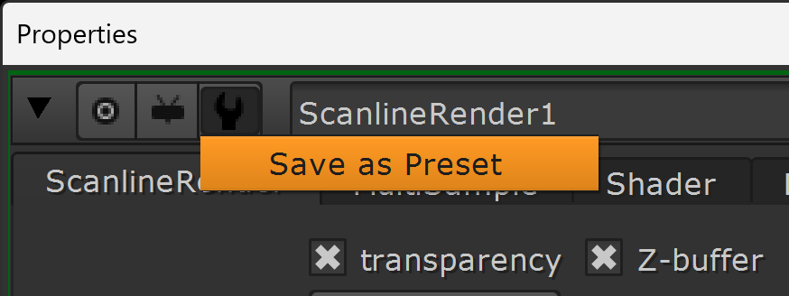
Saving a node preset.
Precompositing
Even when following best practices – as your script grows it might start to become less responsive.
Parts of the script might become too CPU intensive, or you might fill up your machine's RAM and start to experience crashes or failed renders on the farm.
To keep your composite snappy and easy to work with, precompositing sections of it is a great solution.
This is another instance where the practice of keeping a main B-spine, and having the different sections of your comp feed into it via the A-inputs, comes in handy. You can precomposite an A-input before it gets merged into the main B-spine and simply use the precomposite render as the A-input.
By precompositing the A-input instead of precompositing somewhere in the B-stream, you can effectively 'lock off' completed sections of your script. I.e. you won’t have to update the precomposite renders if you change something upstream in the B-spine.
When precompositing, make sure you are rendering:
- All the necessary layers you will need downstream.
- Enough overscan to avoid any cropping issues downstream.
- High enough fidelity, e.g. EXR files without too much compression, and 32-bit for data passes to maintain accuracy.
In-Script Precomposite
If your script is using heavy nodes, i.e. taxing your CPU/GPU, it might be enough to add a Write node inside of your script at the end of the offending A-section and render it to disk.
Then, read in the rendered image sequence and use that downstream instead of the live A-section.
I suggest clearly labelling where you are precompositing with a bright backdrop, and creating a Switch setup for easily changing between the render and the live section:
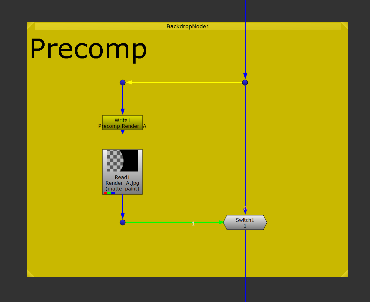
Switch setup for precomps.
Do this for example for heavy ZDefocus nodes, element retimes, or vector-based nodes.
Off-Script Precomposite
However, if your script is crashing due to filling up the RAM, you may need to offload some sections of it into separate precomposite scripts.
In this case, move sections of your composite into a new, empty script (or scripts) and render to disk. Make sure to use a sensible naming convention, describing what your precomposite contains. Then, after rendering out the precomposite(s), only bring the render(s) into your main script.
For special setups such as denoising, and particle systems, I would recommend offloading them into separate scripts every time to keep your main script running efficiently - as they can quickly grind your script to a halt.
Finding The Root Cause
When addressing notes and solving issues with your shot, always try to fix the problem at its source, and not somewhere further downstream.
The further from the source you fix the problem, the more likely it is that the fix will cause new problems in your composite.
For example, let’s say that to patch over an issue, you do some cloning using a RotoPaint node at the end of your script. There’s then a high risk that any changes you make upstream in the area that you’re cloning from will get caught up in that cloning, resulting in duplicate edges or artefacts.
Instead, travel upstream until you find where the problem first appears, and do your fixes there.
Using Proxies
Using the proxy mode or the downsampling (downrez) feature in the Viewer can be helpful when you’re working on high-resolution scans and your computer is struggling a bit.
However, I’ve found that both the proxy mode and the downsampling feature can cause issues where artefacts appear, or certain tools don’t line up with the lower resolution image.
You might be precompositing a section of your script, and pulling your hair out trying to figure out why the render looks different to what you are seeing live in Nuke.
It’s usually due to the proxy mode or downsampling.
In fact, I’ve encountered enough issues with them that I have stopped using them altogether. I literally never use those features anymore.
If you are able to, it’s much better long-term to invest in some extra RAM for your machine, and/or a better graphics card, than to lower the quality of your images.
Managing Nuke’s User Interface
A great thing about Nuke is how customisable it is.
Part of that is how the interface can be shuffled around and adjusted to suit your style of working and your specific preferences.
I find that changing the default settings and layout can be very useful - it can actually help improve your compositing:
Colouring Your Pipes
A great way of making your Nuke scripts visually easier to read is to change one of the default settings in the Nuke preferences: the pipe colours.
Under Edit → Preferences → Node Graph → Arrow, you can adjust the colour of the pipes in your script based on which direction they are flowing. This makes it very quick and easy to identify where a pipe is going.
You can choose any colours you like for the pipes. I have found the following to work well for me:
- Blue for pipes going down. I associate blue with water running down a stream or a waterfall which makes it easy to remember that blue indicates a downward direction.
- Yellow for pipes going to the left. I associate yellow with a sticky note, something to notice. You are generally either heading out from the main pipe to make something new, or heading into a mask input. Yellow indicates that something is happening and you should be aware of it.
- Green for pipes going to the right. I associate green with the OK or Go signals, and trees. You are heading back towards the main pipe to complete your task: your branch is leading back to the tree. Green makes it easy to see where your A-inputs join their B-pipes.
- Red for pipes going up. I associate red with a warning or error. Generally, you should try to avoid having pipes going up in order to keep a natural, organised downward flow in your script. Red makes it easy to spot when a pipe is going where it perhaps should not.
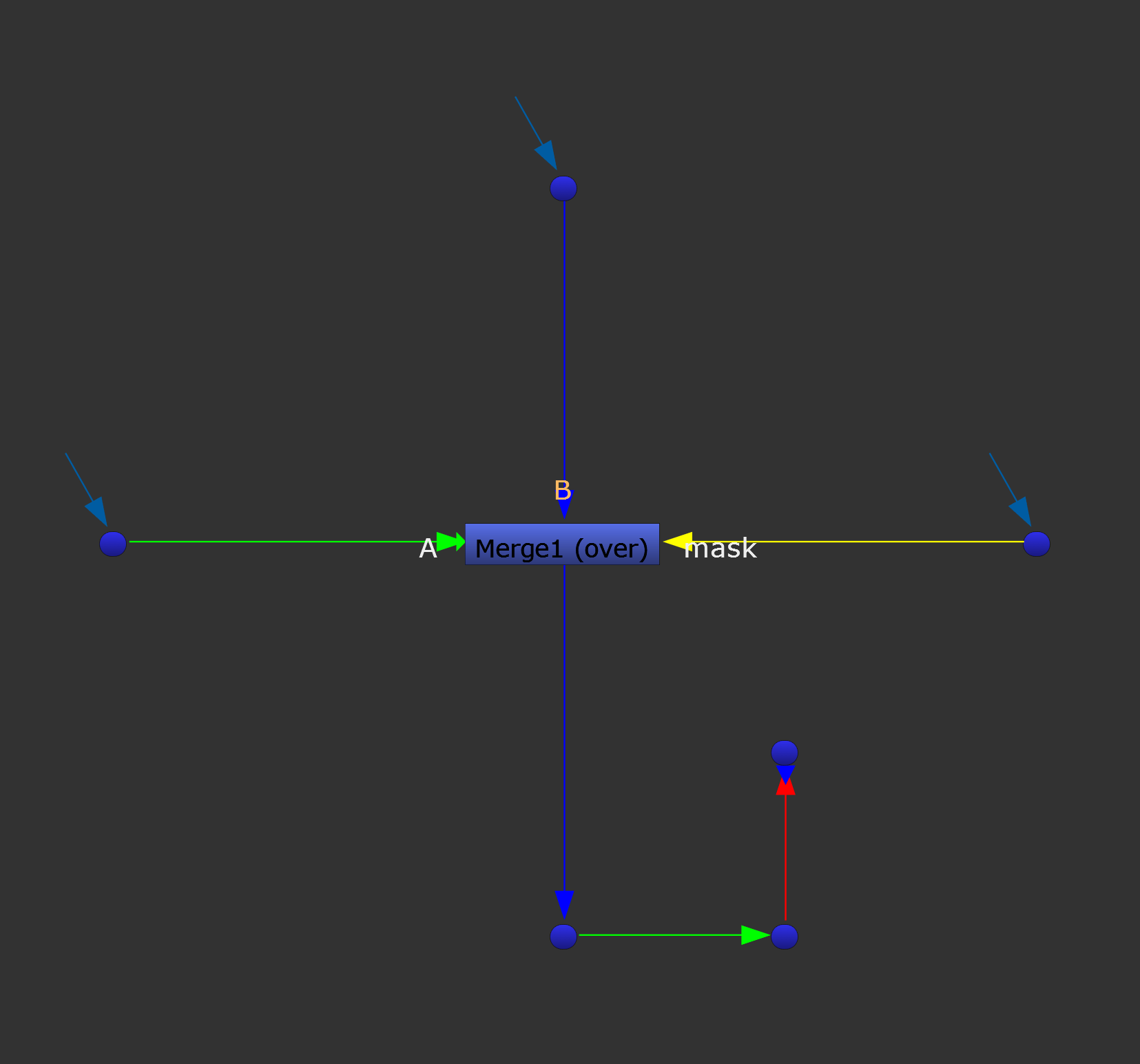
Setting up custom pipe colours makes it easy to see which direction a pipe is going.
Moving The Panels Around
You’re not locked to the default panel layout in Nuke.
There are several different pre-made options in the Workspace menu that you can use, or you can make your own customised layout.
Single Screen Layout
When working with a single screen setup, your main priority for populating the screen space should be the Viewer panel. Make it as large as you can while still being able to comfortably view the other panels.
We are producing images, and the product is king. You’ll want to be able to see as much detail and have as much room to work on the images as possible. How you arrange the rest of the panels is more up to personal preference, but below are a few guidelines.
Unless you are working on ultrawide images, having the Viewer panel take up the entire width of your screen (assuming you have a widescreen monitor) is a waste of horizontal screen real estate. Usually, having the Properties panel off to the right hand side of the Viewer panel is a better option.
The Node Graph does not actually need to take up as much space as you would think. You could reduce its size considerably, and if you need some more space to navigate the Node Graph - or any other panel - hit the spacebar while hovering your mouse over the panel to maximise it.
I find that keeping the Node Graph, Curve Editor, and Dopesheet as tabs in the same panel works great, and unless you have specific needs to view them at the same time, these can be left grouped together.
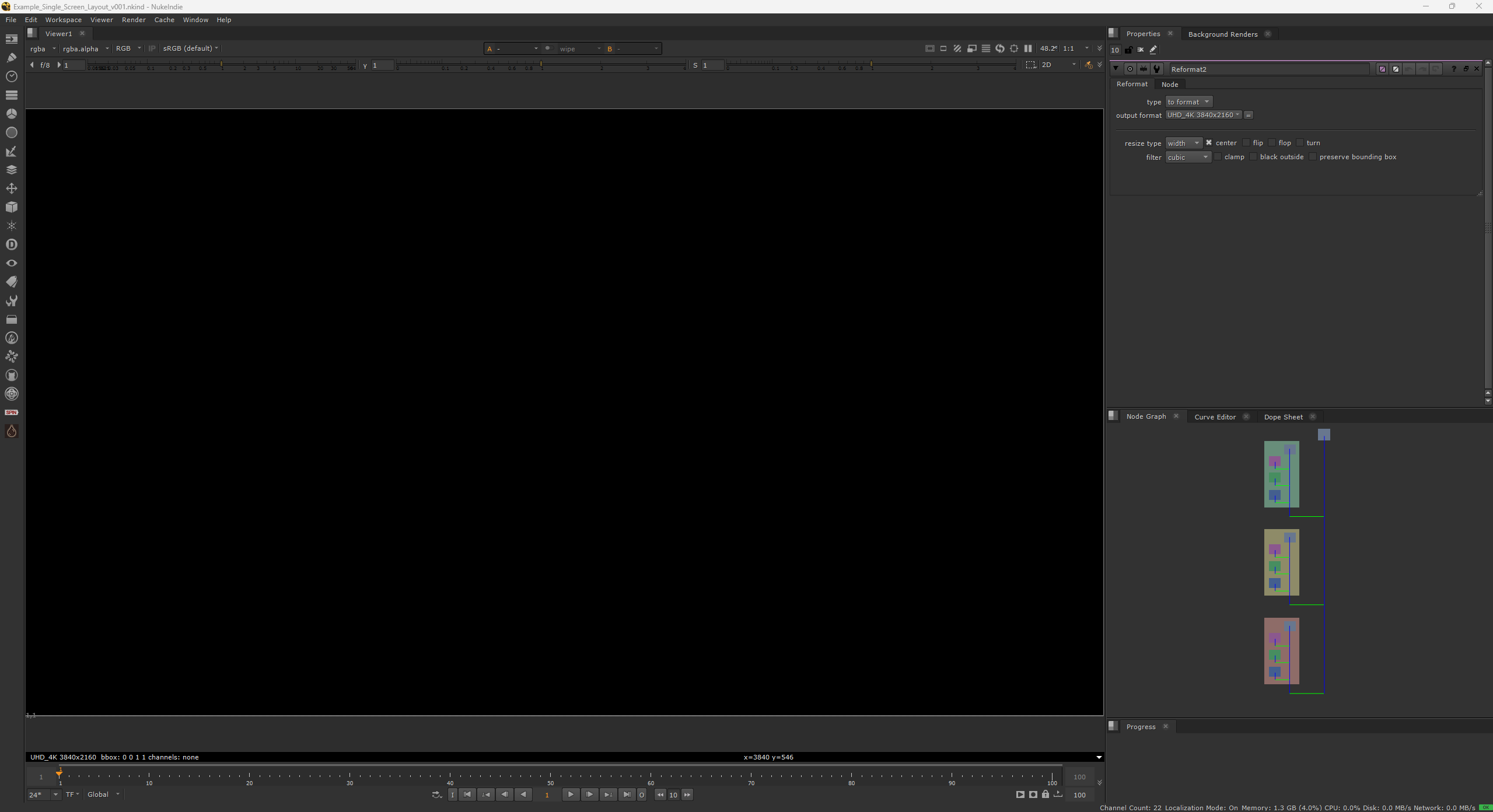
Example of a single screen layout.
Multiple Screens Layout
If you have two or more screens you can really start customising your layout.
Many companies will have two screens per artist, and I would suggest arranging your layout so that the Viewer panel takes up the full screen of the best monitor.
The second screen will then have the Node Graph and the Properties panel.
Maximising the screen space for the Viewer lets you see more detail in your shots and gives you more space to work on the image, for example when rotoscoping, painting, or navigating in 3D space.
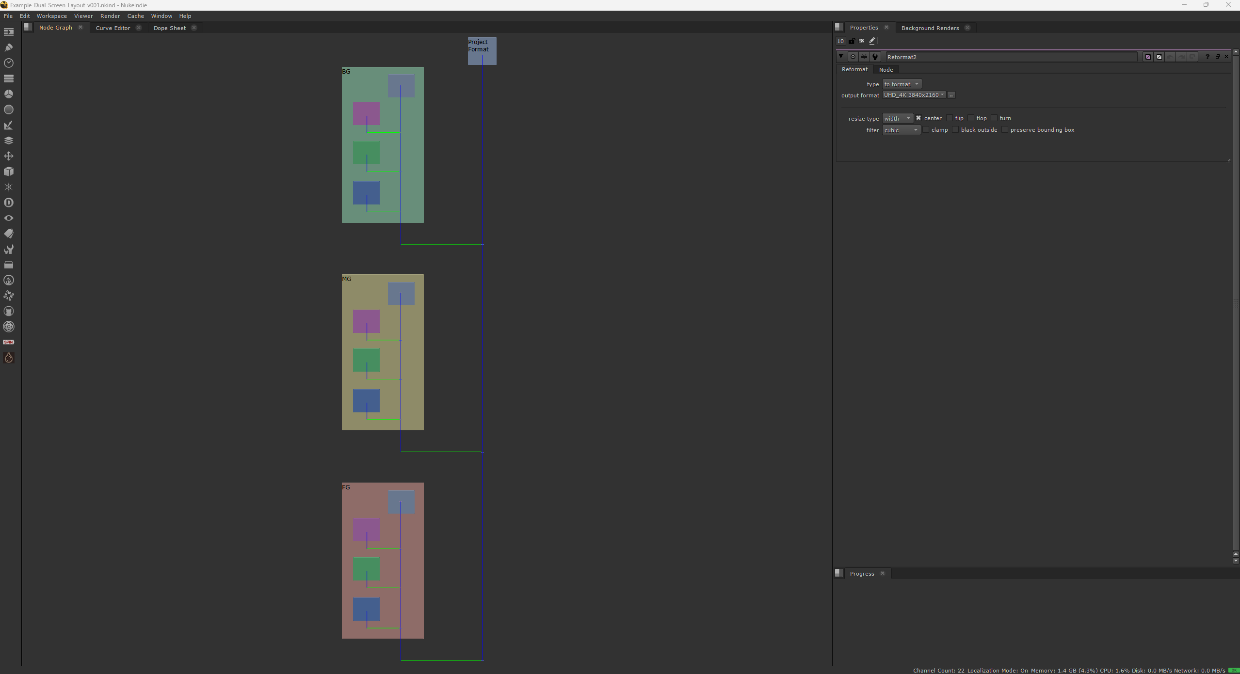
Example of a dual screen layout.
Progress Bar
By default, the progress bar in Nuke is a pop-up window.
Particularly when working on two screens, this pop-up window can accidentally get hidden behind the Viewer panel, which is not ideal.
Instead of having to hide the Viewer panel with the ` key (just below the esc key on UK keyboards) to recover the progress bar every time it gets lost, and then unhide it, I prefer to attach the progress bar to the user interface.
I like to split the properties panel into two panels vertically, add the progress bar to the bottom panel, and reduce its size. That way, it’s always there, easily accessible at a glance, but does not take up much valuable space on the screen.
This may be a small change, but keep in mind that many small changes in total have a great impact.
It’s all about reducing friction in your day-to-day workflow, and this small change means that there is one less frustration to worry about.
Saving A Layout
When you’re happy with your customised layout, make sure to save it for future use.
Click on the Workspace menu → Save Workspace, and give the layout a descriptive name.
Changing The Default Startup Layout
Once you have created and saved your favourite layout, it’s useful to tell Nuke to load up that layout by default.
Not having to change the layout every time you open Nuke will save you thousands of clicks in the long run.
To set a layout as the default startup layout, go to:
Edit → Preferences → Startup → startup workspace
- and choose your default startup layout.
(Alternatively, in older versions of Nuke, when you save your layout, overwrite the Compositing 1 layout which is Nuke's default startup layout).
Simplifying The Properties Panel
The properties panel will by default allow the properties of ten nodes to be open at one time.
If you have more than one node’s properties open at a time, this can cause trouble.
In order to change the properties of the node that you want, you have to highlight either the node itself so that the corresponding properties become selected, or manually select it from the list in the properties panel. Forgetting this can lead to accidentally changing the properties of the wrong node.
To combat this, you could reduce the number of nodes allowed to be open at a time:
Go to the properties panel, and at the top, enter a lower number than 10 in the maxPanels field.
However, a better solution in my opinion is to automatically collapse the properties of the nodes that aren’t selected, displaying only one node’s properties at a time in the properties panel:
Under Edit → Preferences → Control Panels, tick expand/collapse panels in Properties bin to match selection.
That way, you can still have multiple properties open at a time, but reduce the chances of adjusting the wrong one.
And if you want to compare two properties, you can expand them manually in the properties panel, or hit CTRL + double left-click on a node to open its properties in a floating window.
This is great for side-by-side comparison, for copying settings, or for expression linking values between nodes.
Hotkeys and Shortcuts
There are many context dependent hotkeys for speeding up your workflow in Nuke.
For a full list, go to:

I would like to highlight some of the more useful ones that I hit the most:
While Hovering Over The Viewer
- Alt + P to toggle the Viewer Input process.
- Ctrl + A to select all, for example all the points of a rotoscope shape. Also works while hovering over the Node Graph/Curve Editor/Dope Sheet to select all nodes/curves/keyframes.
- Ctrl + Left-click to sample single pixel values in the Viewer.
- Ctrl + Shift + Left-click-and-drag to sample a region of averaged values in the Viewer. You can also use the sample box in the Viewer to measure the number of pixels, as a guide for aligning something. At the bottom of the Viewer it will say how large the sample box is in pixels, e.g. 30 pixels by 50 pixels.
- Ctrl + Alt + Shift + Left-click-and-drag to sample a region of averaged values in the Viewer from the node's input while viewing the output. This means the sampling will not be affected by any changes made by the currently viewed node to the image. This is useful for example when colour picking for keying and grading.
- Ctrl + Right-click to remove the red sample pixel/region from the Viewer. You are welcome.
- E and Shift + E to add or remove feather to the selected Roto shape.
- F to frame the Viewer.
- H to maximise the frame in the Viewer.
- I and O to set Input and Output points on the timeline.
- J, K and L to reverse, stop, and play forward.
- M to overlay the matte channel (alpha channel by default).
- PageUp and PageDown to cycle up and down through the layer list.
- Q to hide/unhide the overlay, e.g. rotoscope shapes.
- S to open up the Viewer settings.
- Shift + Left/Right arrow to jump backwards or forwards on the timeline by a set amount of frames; the default is 10.
- Tab to cycle between 2D and 3D view.
- Z to smooth out selected bezier point(s) on a Roto shape.
While Hovering Over The Node Graph
- Alt + E to hide/unhide expression lines in the Node Graph.
- Alt + K to clone the selected node(s). Alt + Shift + K to declone.
- B to create a Blur node.
- C to create a ColorCorrect node.
- Ctrl + Left-click on the centre of a pipe to create a Dot node connected to the pipe.
- Ctrl + Left-click-and-drag on a node to move it and all of the nodes connected to it upstream at the same time.
- Ctrl + Left-double-click to open a node's property panel in a floating window.
- Ctrl + Left-click-and-drag on the top edge of a Backdrop node to move the backdrop without moving the nodes on top of it.
- Ctrl + Shift + Left-click-and-drag a node on top of another node and let go to swap the two nodes.
- Ctrl + Shift + X to extract selected nodes from the tree.
- Dot (.) to create a Dot node.
- F with nothing selected to frame all the nodes in the Node Graph, or with one or more nodes selected to frame the selection.
- K to create a Copy node.
- L to line up the selected nodes in the Node Graph.
- M to create a Merge node.
- O to create a Roto node.
- P to create a RotoPaint node.
- S to open up the project settings.
- T to create a Transform node.
- Tab to search for nodes.
- Y to connect a node to another node upstream. Select the node you want to connect upwards first, and then Shift select the node you want to connect it to, then press Y.
While Hovering Over The Curve Editor
- Ctrl + Alt + Left-click to add a point to a curve. This hotkey also works the same way on a rotoscope spline in the Viewer.
- H to ease in/out selected curve point(s) horizontally.
- Z to smooth out selected curve point(s).
While Hovering Over The Dope Sheet
- Left-click-and-drag on the left or right edge of the selection box of keyframes to scale the keyframes in either direction.
While Hovering Over A Node's Property Panel
- Arrow keys (Left, Right, Up, Down) to navigate and increase/decrease a knob value. (Left-click the value first to select it).
- Ctrl + Left-click-and-drag to expression link a value to another value.
- Ctrl + Shift + Left-click-and-drag (left or right) over a Grade node's colour wheel (or any colour wheel) to decrease or increase the value. Great for lifting black points.
While Hovering Over Anywhere
- Space while hovering your mouse over a panel to maximise that panel.
Custom Hotkeys
If you find yourself using the same node or gizmo often, you can set a hotkey for it in the menu.py.
Ben McEwan explains how to do that quite nicely in this previously mentioned tutorial.
And that wraps up this guide (which ended up being over 50 pages long)! I hope you found it useful.
For more Nuke tips & tricks, see Nuke.


